![]() Sanitary Microfiltration Spiral-Wound Element
Sanitary Microfiltration Spiral-Wound Element
FR MAX (PVDF 800,000Da)
Synder Filtration’s Microfiltration Elements offer an optimal combination of both flux and rejection in a comprehensive range of MWCO’s. Contact us today to learn more about our complete line of membrane products and services.
FR is Synder’s most popular microfiltration membrane, used particularly throughout the dairy industry for fat removal, microbial removal, and protein fractionation. With a molecular weight cut-off of 800kDa, it is currently the tightest available membrane within the microfiltration line and is a customer favorite for its optimal combination of flux and separation performance. While it is frequently used for sanitary applications such as whey/casein fractionation, fat/microbial removal, beverage sterilization, wine clarification, oat sweetener clarification, and gelatin clarification, it can also be used for industrial applications such as fermentation broth clarification and the removal of large particulates and bacteria from during wastewater treatment.
MAX SERIES BENEFITS
- Conforms to 3-A, FDA, and USDA sanitary standards
- Hot sanitization eliminates chlorine during CIP
- High resistance to pH and temperature
- High resistance to fouling
- Customizable dimensions for unique housings
COMMON APPLICATIONS
- Fat/Microbial removal
- Protein fractionation
Element Specifications


RECOMMENDED OPERATING PARAMETERS
| Pressure | PSI | Bar |
| Max Inlet Pressure | 120 | 8.3 |
| Min Outlet Pressure | 10 | 0.7 |
| Max Differential Pressure per Element | 18 | 1.2 |
| Max Permeate Backpressure | 5 | 0.3 |
Note: Soft start on boost pumps required to minimize pressure/flow shocks to elements.
| Temperature | Fahrenheit | Celsius |
| Max. Operating | 140° | 60° |
| Max. CIP Temperature | 185° | 85° |
| pH Parameters | pH |
| Operating Parameters |
At Max Temp. – 3-10 At Ambient Temp. – 2-10.5 |
| Cleaning Parameters |
At Max Temp. – 2-11 At Ambient Temp. – 2-12 |
| Chlorine | Norm. ppm | Max. ppm |
| Free Chlorine in DF Water or Product | 0 | < 0.1 |
| Chlorine during CIP at: pH 10.8-11.0 and 50°C (PES/PVDF) pH 10.5 and 50°C (PAN) |
150 | 180 |
Note: Maximum chlorine exposure for all elements is 30 minutes per day at pH and temperature conditions listed above.
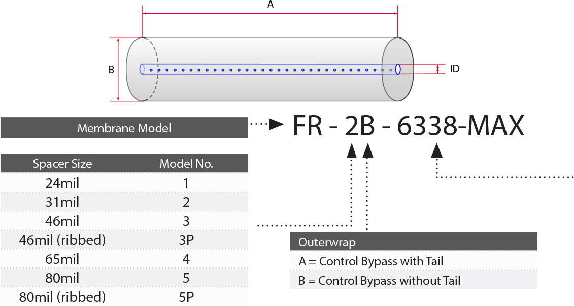
DIMENSIONS & WEIGHT
| Element | Model No. | Diameter (B) in (cm) | Length (A) in (cm) | PWT ID/OD in (cm) | Weight (lb) | Weight (kg) |
| 1.8″ | 1812F | 1.8 | 12 | 0.63 | 1 | 0.5 |
| 2.5″ | 2519 2540F 2540M* |
2.5 2.5 2.5 |
19.25 40 38 |
0.63 0.63 0.75* |
2 4 4 |
0.9 1.8 1.8 |
| 3.8” | 3838 3838.75 3850 3938.75 |
3.8 3.8 3.8 4.0 |
38 38.75 50 38.75 |
0.83 0.83 0.83 0.63 |
10 10 13 10 |
4.5 4.5 5.9 4.5 |
| 4.3” | 4333 4333 4335.5 4336 4338 |
4.3 4.3 4.3 4.3 4.3 |
33 35 35.5 36 38 |
0.83 0.83 0.83 0.83 0.83 |
11 11 11 11 12 |
5.0 5.2 5.2 5.2 5.4 |
| 5.8” | 5838 | 5.8 | 38 | 1.14 | 15 | 7.0 |
| 6.3” | 6338 6324 |
6.3 6.3 |
38 24 |
1.14 1.14 |
16 17 |
7.0 7.7 |
| 6.4” | 6438 6424 |
6.4 6.4 |
38 24 |
1.14 1.14 |
29 18 |
13.2 8.2 |
| 7.8” | 7838 7824 |
7.8 7.8 |
38 24 |
1.14 1.14 |
40 26 |
18.2 11.8 |
| 8” | 8038 8040 8238 |
8.0 8.0 8.2 8.2 8.3 8.3 |
38 40 38 40 38 |
1.14 1.14 1.14 1.14 1.14 1.14 |
38 39 38 40 40 40 |
17.2 17.7 17.2 18.0 18.0 18.0 |
| 9″ | 9838 | 9.8 | 38 | 1.14 | 42 | 19.1 |
| 10” | 10338 | 10.3 | 38 | 1.14 | 50 | 22.7 |
Recommended Element Cross Flow Rate
| Element |
Feed Spacer (in mils)
|
||||||||||
| 1.8″ | m3/hr gpm |
1 4 |
1 5 |
1 6 |
2 7 |
2 7 |
|||||
| 2.5″ | m3/hr gpm |
2 9 |
2 10 |
3 11 |
3 12 |
3 13 |
|||||
| 3.8” | m3/hr gpm |
5 22 |
6 25 |
7 29 |
8 33 |
8 35 |
|||||
| 4.3” | m3/hr gpm |
6 29 |
7 32 |
9 38 |
10 44 |
10 46 |
|||||
| 5.8” | m3/hr gpm |
12 51 |
13 59 |
16 69 |
18 78 |
19 83 |
|||||
| 6.3” | m3/hr gpm |
15 65 |
17 74 |
20 88 |
22 99 |
24 105 |
|||||
| 8” | m3/hr gpm |
21 94 |
24 107 |
29 128 |
33 143 |
35 154 |
|||||
| 10” | m3/hr gpm |
42 184 |
48 213 |
57 250 |
64 283 |
68 299 |
|||||
*Note: The recommended cross flow rate will be subject to differential pressure limitations and specific applications.
Membrane Area(SQ. FT.)
| Element | Model No. |
Feed Spacer (in mils)
|
|||||||||
| 1.8″ | 1812F | 4.3 | 3.6 | 2.9 | 2.1 | 1.8 | |||||
| 2.5” | 2519 2540M 2540F |
15 34 35 |
13 29 30 |
10 22 23 |
8 17 18 |
7 15 16 |
|||||
| 3.8” | 3838 3838.75 3850 |
85 86 100 102 |
72 74 84 89 |
58 59 70 69 |
46 47 52 53 |
38 39 46 47 |
|||||
| 4.3” | 4333 4335 4335.5 4336 4338 |
99 105 107 108 115 |
86 91 93 94 100 |
66 71 72 73 77 |
53 56 57 58 62 |
44 47 48 49 52 |
|||||
| 5.8” | 5838 | 210 | 184 | 147 | 114 | 96 | |||||
| 6.3” | 6324 6338 |
150 246 |
134 220 |
107 176 |
83 136 |
70 115 |
|||||
| 6.4” | 6424 6438 |
157 258 |
140 230 |
112 184 |
83 136 |
74 122 |
|||||
| 7.8” | 7824 7838 |
242 396 |
210 344 |
166 273 |
132 216 |
110 180 |
|||||
| 8” | 8038 8040 8238 8240 8338 8340 |
414 414 441 441 450 450 |
368 368 384 384 400 400 |
287 287 302 302 311 311 |
225 225 238 238 245 245 |
189 189 201 201 207 207 |
|||||
| 9″ | 9838 | N/A | 564 | 440 | 351 | 296 | |||||
| 10” | 10338 | N/A | 620 | 492 | 386 | 326 | |||||
TECHNICAL NOTES
For element sizes not listed, please call or email Synder Filtration for details. We can design an element to fit your exact needs – just specify the element outer diameter (OD) or vessel/housing inner diameter (ID), element inner diameter (ID), and length. Elements are available with or without a controlled bypass tail. Trials should be conducted to determine optimal application conditions.