![]() Nanofiltration TFC Spiral-Wound Element
Nanofiltration TFC Spiral-Wound Element
NFG (600 – 800Da)
Synder Filtration’s Nanofiltration membranes are engineered and designed to provide superior separation performance for various application needs. Known for its stable flux and wide range of rejection to monovolent and divalent ions, Synder’s NF membranes have been developed specifically for specialty process applications.
Synder’s NFG nanofiltration membrane provides high flux and moderate levels of lactose and MgSO4 rejection. With a molecular weight cut-off of 600 to 800 Daltons, NFG is ideal for applications requiring a large amount of salt removal and are commonly used in the dairy industry for milk processing. Other applications include demineralization and concentration of lactose and the desalination of dyes and optical brighteners.
NF SERIES BENEFITS
- Operation at lower pressures than Reverse Osmosis membranes and still achieve excellent rejection of divalent and multivalent ions
- NF membranes greatly reduce levels of hardness, nitrates, sulfates, tannins, turbidity, color, TDS, and moderate levels of salt from feed water streams
Element Specifications


MEMBRANE SPECS
| Model | Polymer | Approx. Molecular Weight Cutoff |
Typical Operating Flux |
Min Lactose Rejection1 |
Avg MgSO4 Rejection2 |
Avg NaCl Rejection3 |
| NFG | Proprietary PA TFC | 600-800Da | 55-60 GFD | 60.0% | 50.0% | 10.0% |
1Test Conditions: 2,000ppm Lactose solution at 110psi (760kPa) operating pressure, 77°F (25°C)
2Test Conditions: 2,000ppm MgSO4 solution at 110psi (760kPa) operating pressure, 77°F (25°C)
3Test Conditions: 2,000ppm NaCl solution at 110psi (760kPa) operating pressure, 77°F (25°C)
RECOMMENDED OPERATING PARAMETERS
| Operating Parameters | |
| Maximum Operating Pressure | 600psi (4,137kPa) if T < 95°F (35°C) 435psi (3,000kPa) if T > 95°F (35°C) |
| Maximum Temperature | 50°C (122°F) |
| pH Range @ Max Temperature | 4-9 |
| pH Range @ Ambient Temperature | 4-10 |
| Cleaning Parameters | |
| Maximum Temperature (Short term <30min) | 50°C (122°F) |
| pH Range @ Max Temperature | 3-10 |
| pH Range @ Ambient Temperature | 3-10.5 |
| Pressure Drop | PSI |
| Maximum per Element | 15psi (103kPa) |
| Maximum per Housing | 60psi (414kPa) |
| Chlorine Tolerance |
| 500ppm hours, dechlorination recommended |
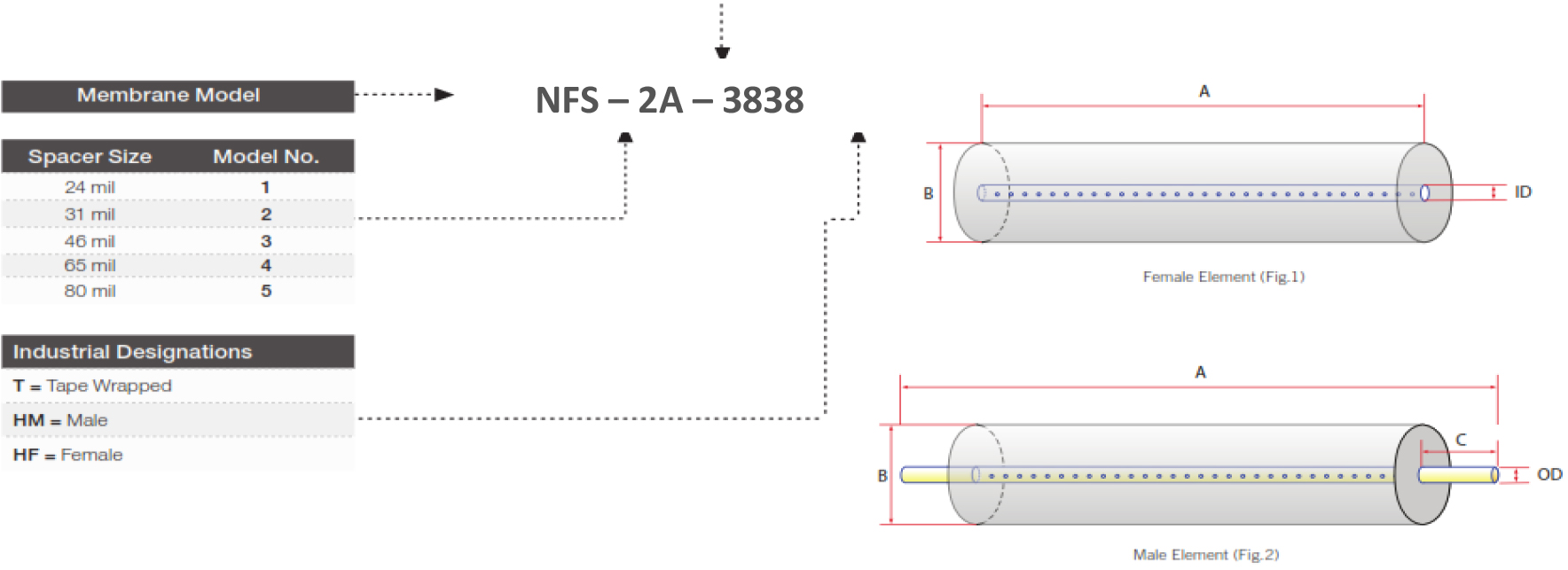
Element Dimensions & Weight
| Element | Model No. | Diameter (B) in(cm) | Length (A) in(cm) | P.W.T. ID/OD in(cm) | Tube Extension (C) in (cm) | Dry Weight lb(kg) |
| 1.8″ | 1812TM | 1.8″(4.6) | 11.75″(29.8) | 0.675″(1.71) | 0.75″(1.90) | 1.0(0.9) |
| 2.5″ | 2519HF 2540TM 2540HF 2540HM |
2.4″(6.1) 2.4″(6.1) 2.4″(6.1) 2.4″(6.1) |
19.0″(48.3) 40.0″(101.6) 40.0″(101.6) 40.0″(101.6) |
0.625″(1.59) 0.75″(1.90) 0.625″(1.59) 0.75″(1.90) |
– 1.0″ (2.54) – 1.0 (2.54) |
3.0(1.4) 6.0(2.7) 6.0(2.7) 6.0(2.7) |
| 4″ | 4040TM 4040HM 4040HF |
3.9″ (9.9) 3.9″ (9.9) 3.9″ (9.9) |
40.0″ (101.6) 40.0″ (101.6) 40.0″ (101.6) |
0.75″ (1.90) 0.75″ (1.90) 0.625″ (1.59) |
– 1.0″ (2.54) – |
12.0(5.5) 12.0(5.5) 12.0(5.5) |
| 8″ | 8040 | 7.9″ (20.1) | 40.0″ (101.6) | 1.125″ (2.86) | – | 35.0(15.9) |
Recommended Element Cross Flow Rate
| Element | Feed Spacer (in mils)
|
||||||||||
| 1.8″ | m3/hr gpm |
0.4 1.8 |
0.5 2.0 |
0.6 2.4 |
0.6 2.5 |
0.6 2.6 |
|||||
| 2.5″ | m3/hr gpm |
1.2 5 |
1.4 6 |
1.6 7 |
1.8 8 |
2.1 9 |
|||||
| 4″ | m3/hr gpm |
2 10 |
4 18 |
5 21 |
5 23 |
6 24 |
|||||
| 8″ | m3/hr gpm |
10 43 |
11 48 |
13 55 |
14 61 |
15 64 |
|||||
The recommended cross flow rate will be subject to differential pressure limitations and specific applications.
NF Membrane Area(SQ. FT.)
| Element | Feed Spacer (in mils)
|
|||||||||
| 1812TM | 4 | 3.4 | 2.6 | 2.0 | 1.6 | |||||
| 2540HF | 35 | 30 | 23 | 17 | 15 | |||||
| 2540HM | 33 | 28 | 21 | 16 | 14 | |||||
| 4040HF | 99 | 87 | 68 | 51 | 43 | |||||
| 4040HM | 96 | 82 | 64 | 50 | 42 | |||||
| 8040HF | 440 | 380 | 293 | 227 | 193 | |||||
TECHNICAL NOTES
For element sizes not listed, please call or email Synder Filtration for details. We can design an element to fit your exact needs – just specify the element outer diameter (OD) or vessel/housing inner diameter (ID), element inner diameter (ID), and length. Elements are also available with or without a controlled bypass tail. Additional feed spacers are also available. Trials should be conducted to determine optimal application conditions.