![]() Industrial Ecoat A62-F7940HA
Industrial Ecoat A62-F7940HA
PVDF 500kDa
With over 20 years of experience in the ECoat industry, Synder Filtration has proven to be one of the top suppliers of membrane technology when it comes to Ultrafiltration (UF) elements, anode cells, and EDUF systems. As a manufacturer of both custom membranes and systems, we strive to provide quality products and reliable service for our customers around the world. With a full range of molecular weight cutoffs and element sizes for both cathodic and anodic paint baths, Synder can easily outfit any ECoat paint line with reliable ultrafiltration membrane elements.
Electrocoat Industry
Cathodic Paint Recovery – Synder’s V-Series of ultrafiltration membranes have a proprietary hydrophilic charge that… [read more]
Other applications include cathodic paint recovery, anodic paint recovery, industrial wastewater processes, etc.
| Specifications | |
| Size: | 8” Nominal |
| Outerwrap: | FG Hard Wrap with Dual End Seals |
| Element Design: | Spiral |
| Membrane: | PVDF 500kDa |
| Membrane Area: | 318 ft² (29.5 m²) |
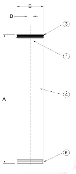
| Diameter: | 7.90” (200.7mm) |
| Overall Length: | 40.00” (1016.0mm) |
| Body Length: | 40.00” (1016.0mm) |
| Weight: | 42 ± 1.0 lb (19.1 ± 0.5 kg) |
| Housing Model: | N/A |
| PERMEATE CAPACITIES | |
| Permeate Output Steady State with Anodic Paint GPM (LPM) | 4.65 ± 10% (17.6 ± 10%) |
| OPTIMAL DESIGN PARAMETERS | |
| Feed Rate: | 80 GPM (303 LPM) |
| Element Inlet PSI: | 50 PSIG (345 KPA) |
| Pressure Drop: | 30 PSIG (207 KPA) |
NOTE: Element performance may be affected by variances in operating parameters and feed chemistry.
| ELEMENT LIMITS | |
| pH Range: | 1-11 |
| Feed Rate: | 70 / 90 GPM (265 / 340 LPM) |
| Inlet Pressure: | 45 / 75 PSIG (310 / 517 KPA) |
| Pressure Drop: | 25 / 35 PSIG (172 / 241 KPA) |
| Operation Temp: | 120°F (48°C) |
INSTALLATION PROCEDURES
- Remove the flow meter/assembly from the housing top cap. Store in a safe place to prevent damage.
- Remove the Victaulic coupling from the top cap.
- Lift the top cap off the housing. In most cases the element will lift up with the top cap. If it does not, pull the spent element out by the permeate tube extension, ATD, or by removing the housing and bottom cap to push the element out.
- Carefully remove the element from its storage bag. For elements with rubber seals, ensure they are properly installed by lubricating with glycerine.
- Replace the O-ring on your top cap with the new O-ring supplied with your element and lubricate them with glycerine. A vial of glycerine is included with each shipment.
- Eliminate the residual paint from the housing. Fill the housing approximately 1/3 full with DI/RO water.
- Insert the bottom plug into the end of the element without the rubber seal(s). For elements with no rubber seal, insert bottom plug into any end.
- Insert the element into the housing, bottom end plug first. Do not force the element. For elements with tape wrap, you may trim the tape until it has a snug fit.
- Gently push the element to make sure the element is seated on the bottom of the housing. Make sure the permeate tube is completely submerged in DI/RO water.
- Carefully insert the top cap connector into the permeate tube. Replace the Top Cap and tighten the bolts. Reinstallthe flow meter/bypass assembly and tighten the union connec-tions.
- Circulate DI/RO water through the element for 15 minutes in the CIP loop. Purge to drain, and then refill with fresh DI/RO water. If this is not possible, soak the element in DI/RO water for at least one hour, purge to drain, and re-fill the housing with fresh DI/RO water.
- Open both the paint permeate to rinse valve and the paint return valve.
- Start paint feed pump and slowly open paint feed valve (to fully open in 3-5 minutes). Adjust inlet pressure to a minimum of 50psi.
Warning: When operating on paint or cleaning, the appropriate permeate transport valve must be 100% open. When operating on paint, the “Permeate to Rinse” valve must be 100% open. When cleaning, the “Permeate to CIP tank” valve must be 100% open. Throttling or closing any permeate valve while it’s in operation can cause Leakers and Smokers and will void our Membrane Material & Workmanship warranty. - After the system runs for a few minutes it may be necessary to re-adjust the pressures until the system balances out and the pressure/flow stabilize.
CLEANING PROCEDURES
Spiral Elements should be cleaned when the permeate rate has declined between 20%-30% from the steady state permeate rate that was recorded when either the element was installed initially or last cleaned. Steady state permeate rate is the rate that you record about 15-20 minutes after the element is initially put on the paint, or after the element has been thoroughly cleaned.
Note: The permeate rate should never drop more than 30% before an element is cleaned.
- When initially cleaning an element, you should flush the paint from the element (preferably back to the paint tank) with UF permeate. If your system is large enough, and time permits, do this 2 more times. This helps with the cleaning process and helps recover as much paint as possible.
- If UF permeate is unavailable, make up a solution of artificial permeate using DI/RO water and acetic acid. Adjust the heat and pH of the solution to that of the paint. Flushing the paint from the element with cold DI/RO water, you can “set” the paint on the element surface, making it difficult to clean. Confirm that this is acceptable with the paint manufacturer before proceeding.
- After flushing the paint from the element, flush the element to drain. Start with a full heated cleaning tank of DI/RO water, pH adjusted to pH of the paint. Once you have started flushing the element to drain, open the DI/RO water fill valve to the cleaning tank to maintain the level in the cleaning tank. This will allow you to thoroughly flush the element to drain, while gradually lowering the temperature of the water.
- When the flush water is reasonably clean from the element , slowly close the cleaning pump discharge valve and stop the pump.
SPECIAL RECOMMENDATIONSSynder Filtration has formulated a concentrated cleaning product for use with our membranes and other spiral elements. The concentrate ratio is 1:99 and does not require the use of any solvents; uses muriatic acid (acetic and formic acid may be substituted for muriatic) and is usually effective in 60 minutes or less. The key to its success is cleaning at a pH of 2.0 to 2.2, maintaining a temperature between 100°F and 110°F, and cleaning before the permeate rate has decline too far. Contact us for more information on cleaning products and guidelines.
STORAGE PROCEDURES
6 Months or Less (Short Term)
Immediately following the final CIP flush, the system should be filled with 1% Sodium Metabisulfite (MBS) solution with a pH of 4.0-5.0. Every 7-10 days the following procedure should be performed:
- Drain MBS solution from the system and flush to drain with clean water.
- Run a caustic wash. (pH 10.8-11.0; 120-122°F; 15-20 minutes)
- Flush to drain with clean water.
- Recharge the system with a fresh bath of MBS.
Longer than 6 Months (Long Term)
A long term shutdown (over 6 months) can be handled easily and efficiently. This involves the removal of elements from the system, soaking them in preservative solution (vertically if possible), and sealing in a plastic bag for future use.
- The preservative solution should include:
20% Glycerine
2% Sodium Metabisulfite
pH 4.0-5.0 - Remove the element from the vessel, drain the elements in a vertical position to avoid extensive dilution of the preservative solution.
- Place the element in a preservative for a minimum of 15 minutes.
- Remove the element from the preservative and allow it to drain for approximately 10 seconds, then place the element back in the bag.
- Seal the bag either via heat seal or waterproof tape. This should be done well to prevent any leakage during storage/transport.
- Depending on the number of elements, the preservative solution may become diluted. In that event, add more preservative to maintain pH 4.0-5.0.
- Element storage in 50°F – 59°F (10°C – 15°C) will increase storage life of the elements. If refrigeration is possible, it is highly recommended by Synder Filtration.
- Contact Synder Filtration prior to storing any elements to discuss any remaining element warranty.
Synder Filtration believes the above information and data herein to be accurate. However, said information is offered in good faith, but without guarantee of results since the conditions and methods used are beyond our control. Synder Filtration assumes no liability as to the application of the previously mentioned guidelines.
TECHNICAL NOTES
For element sizes not listed, please call or email Synder Filtration for details. We can design an element to fit your exact needs – just specify the element outer diameter (OD) or vessel/housing inner diameter (ID), element inner diameter (ID), and length. Elements are also available with or without a controlled bypass tail. Additional feed spacers are also available. Trials should be conducted to determine optimal application conditions.