![]() Industrial Microfiltration Spiral-Wound Element
Industrial Microfiltration Spiral-Wound Element
FR (PVDF 800kDa)
Synder Filtration’s Microfiltration Elements offer an optimal combination of both flux and rejection in a comprehensive range of MWCO’s. Contact us today to learn more about our complete line of membrane products and services.
FR is Synder’s most popular microfiltration membrane, used particularly throughout the dairy industry for fat removal, microbial removal, and protein fractionation. With a molecular weight cut-off of 800kDa, it is currently the tightest available membrane within the microfiltration line and is a customer favorite for its optimal combination of flux and separation performance. While it is frequently used for sanitary applications such as whey/casein fractionation, fat/microbial removal, beverage sterilization, wine clarification, oat sweetener clarification, and gelatin clarification, it can also be used for industrial applications such as fermentation broth clarification and the removal of large particulates and bacteria from during wastewater treatment.
INDUSTRIAL SERIES BENEFITS
- Good resistance to pH and temperature
- High resistance to fouling
- Customizable dimensions for unique housings
COMMON APPLICATIONS
- Fat/Microbial removal
- Protein fractionation
Element Specifications


RECOMMENDED OPERATING PARAMETERS
| Membrane Type | |
| Proprietary PVDF | Spiral-Wound with netted outerwrap or fiber glass hardshell (FRP) |
| Pressure | PSI | Bar |
| Max Inlet Pressure | 116 | 8.0 |
| Min Outlet Pressure | 10 | 0.7 |
| Max Differential Pressure per Element | 18 | 1.2 |
| Max Permeate Backpressure | 5 | 0.3 |
Note: Soft start on boost pumps required to minimize pressure/flow shocks to elements.
| Temperature | Fahrenheit | Celsius |
| Max. Operating | 122° | 50° |
| Max. CIP Temperature | 122° | 50° |
| pH Parameters | pH |
| pH Range during Operation at 25°C Max | 1.0-11.0 |
| pH Range during CIP Operation at 50°C Max | 2.0-11.0 |
| Peroxide | Max ppm. |
| Free Peroxide in Product During Operation | |
| Peroxide as a sanitizer at 25°C Max, pH6-7, 10minutes recirculation | 0.1% |
| Chlorine | Norm PPM | Max PPM |
| Free Chlorine During Operation | 0 | <0.1 |
| Chlorine During CIP at pH10.8-11.0 and 50°C | 150 | 180 |
Note: Maximum chlorine exposure for all elements is 30 minutes per day at pH and temperature conditions listed above.
DIMENSIONS & WEIGHT
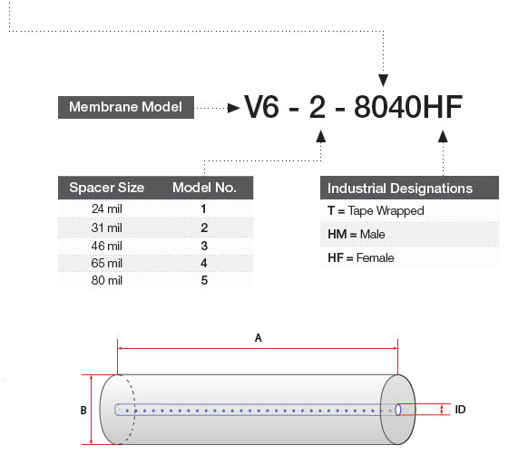
| Element | Model No. | Diameter (B) in (cm) | Length (A) in (cm) | PWT ID/OD in (cm) | Tube Extension (C) in (cm) | Dry Weight lb (kg) |
| 1.8″ | 1812TM | 1.8” (4.6) | 11.75” (29.8) | 0.665” (1.71) | 0.75” (perm) 1.00” (plug) |
1.0 (.45) |
| 2.5″ | 2540TM 2540HF 2540HM |
2.4” (6.1) 2.4” (6.1) 2.4” (6.1) |
40.0” (101.6) 40.0” (101.6) 40.0” (101.6) |
0.75” (1.90) 0.625” (1.59) 0.75” (1.90) |
1.00” (2.54) – 1.00” (2.54) |
4.0 (1.8) 4.0 (1.8) 4.0 (1.8) |
| 4″ | 4040TM 4040HM 4040HF |
3.9” (9.9) 3.9” (9.9) 3.9” (9.9) |
40.0” (101.6) 40.0” (101.6) 40.0” (101.6) |
0.75” (1.90) 0.75” (1.90) 0.625” (1.59) |
1.00” (2.54) 1.00” (2.54) – |
12.0 (5.5) 12.0 (5.5) 12.0 (5.5) |
| 8″ | 7940HF 8040HF |
7.9” (20.1) 7.9” (20.1) |
40.0” (101.6) 40.0” (101.6) |
1.138” (2.89) 1.125” (2.86) |
– – |
35.0 (15.9) 35.0 (15.9) |
Recommended Element Cross Flow Rate
| Element | Feed Spacer (in mils)
|
||||||||||
| 1.8″ | m3/hr gpm |
0.7 3 |
0.8 3 |
0.9 4 |
1.0 4 |
1.1 5 |
|||||
| 2.5″ | m3/hr gpm |
1.3 6 |
1.5 7 |
1.8 8 |
2.0 9 |
2.1 9 |
|||||
| 4.0″ | m3/hr gpm |
3 15 |
4 17 |
5 20 |
5 23 |
5 24 |
|||||
| 8″ | m3/hr gpm |
15 66 |
17 75 |
20 89 |
23 99 |
24 105 |
|||||
*Note: The recommended cross flow rate will be subject to differential pressure limitations and specific applications.
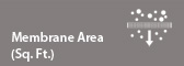
Membrane Area(SQ. FT.)
| Element | Feed Spacer (in mils)
|
|||||||||
| 1812TM | 3.1 | 2.7 | 2.1 | 1.6 | 1.3 | |||||
| 2540M | 28 | 24 | 20 | 16 | 13 | |||||
| 2540F | 30 | 26 | 22 | 17 | 14 | |||||
| 4040M | 81 | 72 | 58 | 46 | 39 | |||||
| 4040F | 86 | 75 | 61 | 49 | 41 | |||||
| 7940F | 379 | 335 | 268 | 210 | 178 | |||||
| 8040F | 379 | 335 | 268 | 210 | 178 | |||||
TECHNICAL NOTES
For element sizes not listed, please call or email Synder Filtration for details. We can design an element to fit your exact needs – just specify the element outer diameter (OD) or vessel/housing inner diameter (ID), element inner diameter (ID), and length. Elements are also available with or without a controlled bypass tail. Additional feed spacers are also available. Trials should be conducted to determine optimal application conditions.