![]() Industrial UF Membrane
Industrial UF Membrane
PY (PAN 100kD) Industrial Specsheet
STANDARD SERIES BENEFITS
- Wide range of MWCO’s available
- Good pH and temperature resistance
- High resistance to fouling
- Customizable dimensions for unique housings
Element Specifications


RECOMMENDED OPERATING PARAMETERS
| Pressure | PSI | Bar |
| Max Inlet Pressure | 116 | 8.0 |
| Min Outlet Pressure | 10 | 0.7 |
| Max. Pressure Drop per Element | 18 | 1.2 |
| Max Permeate Backpressure | 5 | 0.3 |
| Temperature | Fahrenheit | Celsius |
| Max. Continuous Operation | 122° | 50° |
| Max. CIP Temperature | 122° | 50° |
| pH Parameters | pH |
| pH Range during Operation at 25°C Max | 1.0-11.0 |
| pH Range during CIP Operation at 50°C Max | 2.0-11.0 |
| Chlorine | Norm PPM | Max PPM |
| Free Chlorine in DF Water or Product |
0 | <0.1 |
| Chlorine during CIP at pH 10.8-11.0 and 50°C |
150 | 180 |
| Peroxide | Max ppm. |
| Free Peroxide in Product During Operation | <3 ppm |
| Peroxide as a sanitizer at 25°C Max, pH6-7, 10minutes recirculation | 0.1% |
Note: Trials should be made to determine temperature and viscosity effects. Ribbed
spacers are also available for high solids applications.
Recommended Element Cross Flow Rate
| Element | Feed Spacer (in mils)
|
||||||||||
| 1.8″ | m3/hr gpm |
0.7 3 |
0.8 3 |
0.9 4 |
1.0 4 |
1.1 5 |
|||||
| 2.5″ | m3/hr gpm |
1.3 6 |
1.5 7 |
1.8 8 |
2.0 9 |
2.1 9 |
|||||
| 4.0″ | m3/hr gpm |
3 15 |
4 17 |
5 20 |
5 23 |
5 24 |
|||||
| 8″ | m3/hr gpm |
15 66 |
17 75 |
20 89 |
23 99 |
24 105 |
|||||
*Note: The recommended cross flow rate will be subject to differential pressure limitations and specific applications.
Membrane Area(SQ. FT.)
| Element | Feed Spacer (in mils)
|
|||||||||
| 1812TM | 3.1 | 2.7 | 2.1 | 1.6 | 1.3 | |||||
| 2540HF | 28 | 24 | 20 | 16 | 13 | |||||
| 2540HM | 30 | 26 | 22 | 17 | 14 | |||||
| 4040HM | 81 | 72 | 58 | 46 | 39 | |||||
| 4040HF | 86 | 75 | 61 | 49 | 41 | |||||
| 7940HF | 379 | 335 | 268 | 210 | 178 | |||||
| 8040HF | 379 | 335 | 268 | 210 | 178 | |||||
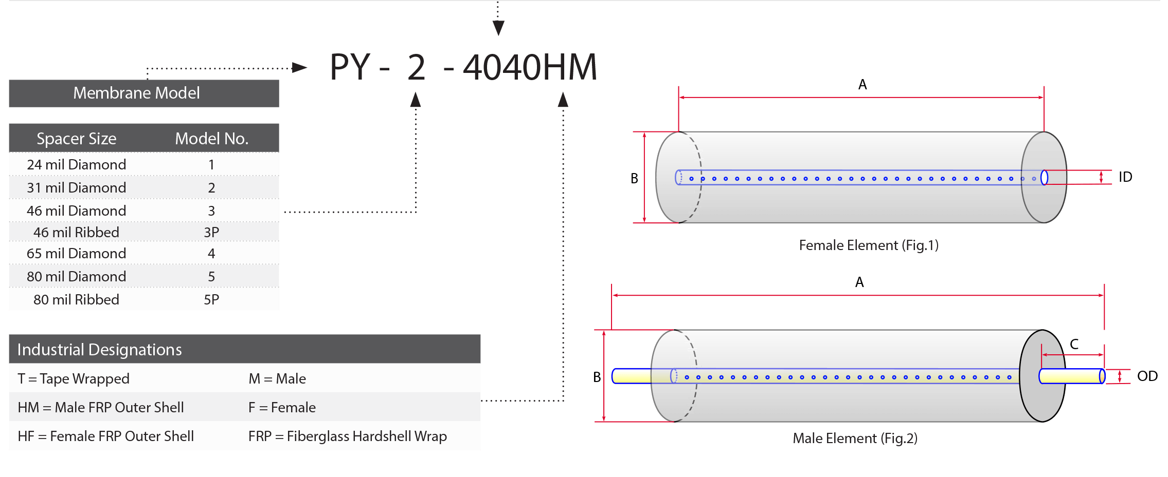
DIMENSIONS & WEIGHT
| Element | Model No. | Diameter (B) in (cm) | Length (A) in (cm) | PWT ID/OD in (cm) | Tube Extension (C) in (cm) | Dry Weight lb (kg) |
| 1.8″ | 1812TM | 1.8” (4.6) | 11.75” (29.8) | 0.675” (1.71) | 0.75” (perm) 1.00” (plug) |
1.0 (.45) |
| 2.5″ | 2540TM 2540HF 2540HM |
2.4” (6.1) 2.4” (6.1) 2.4” (6.1) |
40.0” (101.6) 40.0” (101.6) 40.0” (101.6) |
0.75” (1.90) 0.625” (1.59) 0.75” (1.90) |
1.00” (2.54) – 1.00” (2.54) |
4.0 (1.8) 4.0 (1.8) 4.0 (1.8) |
| 4″ | 4040TM 4040HM 4040HF |
3.9” (9.9) 3.9” (9.9) 3.9” (9.9) |
40.0” (101.6) 40.0” (101.6) 40.0” (101.6) |
0.75” (1.90) 0.75” (1.90) 0.625” (1.59) |
1.00” (2.54) 1.00” (2.54) – |
12.0 (5.5) 12.0 (5.5) 12.0 (5.5) |
| 8″ | 7940HF 8040HF |
7.9” (20.1) 7.9” (20.1) |
40.0” (101.6) 40.0” (101.6) |
1.138” (2.89) 1.125” (2.86) |
– – |
35.0 (15.9) 35.0 (15.9) |
TECHNICAL NOTES
For element sizes not listed, please call or email Synder Filtration for details. We can design an element to fit your exact needs – just specify the element outer
diameter (OD) or vessel/housing inner diameter (ID), element inner diameter (ID), and length. Elements are available with or without a controlled bypass tail.
Additional feed spacers are also available.
Trials should be conducted to determine optimal application conditions.
Refer to installation, cleaning, and storage procedures for more details.