![]() Industrial UF Membrane
Industrial UF Membrane
BX (PVDF 250kD) Industrial Specsheet
STANDARD SERIES BENEFITS
- Wide range of MWCO’s available
- Good pH and temperature resistance
- High resistance to fouling
- Customizable dimensions for unique housings
Element Specifications
RECOMMENDED OPERATING PARAMETERS
| Pressure | PSI | Bar |
| Max Inlet Pressure | 116 | 8.0 |
| Min Outlet Pressure | 10 | 0.7 |
| Max. Pressure Drop per Element | 18 | 1.2 |
| Max Permeate Backpressure | 5 | 0.3 |
| Temperature | Fahrenheit | Celsius |
| Max. Continuous Operation | 122° | 50° |
| Max. CIP Temperature | 122° | 50° |
| pH Parameters | pH |
| pH Range during Operation at 25°C Max | 1.0-11.0 |
| pH Range during CIP Operation at 50°C Max | 2.0-11.0 |
| Chlorine | Norm PPM | Max PPM |
| Free Chlorine in DF Water or Product | 0 | <0.1 |
| Chlorine during CIP at pH 10.8-11.0 and 50°C | 150 | 180 |
| Peroxide | Max ppm. |
| Free Peroxide in Product During Operation | <3 ppm |
| Peroxide as a sanitizer at 25°C Max, pH6-7, 10minutes recirculation | 0.1% |
Note: Trials should be made to determine temperature and viscosity effects. Ribbed spacers are also available for high solids applications.
Recommended Element Cross Flow Rate
| Element | Feed Spacer (in mils)
|
||||||||||
| 1.8" | m3/hr gpm |
0.7 3 |
0.8 3 |
0.9 4 |
1.0 4 |
1.1 5 |
|||||
| 2.5" | m3/hr gpm |
1.3 6 |
1.5 7 |
1.8 8 |
2.0 9 |
2.1 9 |
|||||
| 4.0" | m3/hr gpm |
3 15 |
4 17 |
5 20 |
5 23 |
5 24 |
|||||
| 8" | m3/hr gpm |
15 66 |
17 75 |
20 89 |
23 99 |
24 105 |
|||||
*Note: The recommended cross flow rate will be subject to differential pressure limitations and specific applications.
Membrane Area(SQ. FT.)
| Element | Feed Spacer (in mils)
|
|||||||||
| 1812TM | 3.1 | 2.7 | 2.1 | 1.6 | 1.3 | |||||
| 2540HF | 28 | 24 | 20 | 16 | 13 | |||||
| 2540HM | 30 | 26 | 22 | 17 | 14 | |||||
| 4040HM | 81 | 72 | 58 | 46 | 39 | |||||
| 4040HF | 86 | 75 | 61 | 49 | 41 | |||||
| 7940HF | 379 | 335 | 268 | 210 | 178 | |||||
| 8040HF | 379 | 335 | 268 | 210 | 178 | |||||
DIMENSIONS & WEIGHT
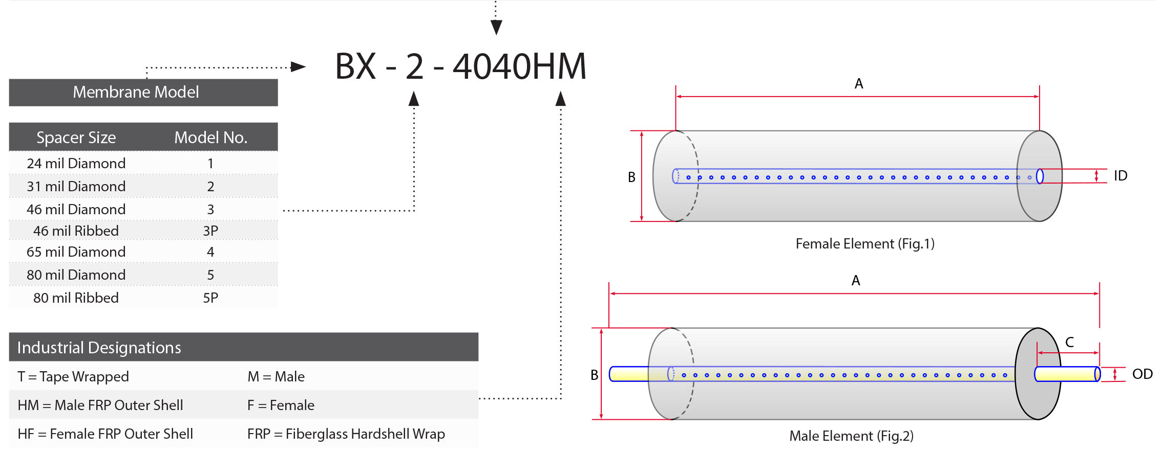
| Element | Model No. | Diameter (B) in (cm) | Length (A) in (cm) | PWT ID/OD in (cm) | Tube Extension (C) in (cm) | Dry Weight lb (kg) |
| 1.8" | 1812TM | 1.8” (4.6) | 11.75” (29.8) | 0.675” (1.71) | 0.75” (perm) 1.00” (plug) |
1.0 (.45) |
| 2.5" | 2540TM 2540HF 2540HM |
2.4” (6.1) 2.4” (6.1) 2.4” (6.1) |
40.0” (101.6) 40.0” (101.6) 40.0” (101.6) |
0.75” (1.90) 0.625” (1.59) 0.75” (1.90) |
1.00” (2.54) – 1.00” (2.54) |
4.0 (1.8) 4.0 (1.8) 4.0 (1.8) |
| 4" | 4040TM 4040HM 4040HF |
3.9” (9.9) 3.9” (9.9) 3.9” (9.9) |
40.0” (101.6) 40.0” (101.6) 40.0” (101.6) |
0.75” (1.90) 0.75” (1.90) 0.625” (1.59) |
1.00” (2.54) 1.00” (2.54) – |
12.0 (5.5) 12.0 (5.5) 12.0 (5.5) |
| 8" | 7940HF 8040HF |
7.9” (20.1) 7.9” (20.1) |
40.0” (101.6) 40.0” (101.6) |
1.138” (2.89) 1.125” (2.86) |
– – |
35.0 (15.9) 35.0 (15.9) |

TECHNICAL NOTES
For element sizes not listed, please call or email Synder Filtration for details. We can design an element to fit your exact needs – just specify the element outer diameter (OD) or vessel/housing inner diameter (ID), element inner diameter (ID), and length. Elements are available with or without a controlled bypass tail. Additional feed spacers are also available.
Trials should be conducted to determine optimal application conditions.
Refer to installation, cleaning, and storage procedures for more details.
Applications
Similar Membranes

questions? Fill out this form. We’ll contact you within 24 hours!
Resources
MEMBRANE RESOURCES
- Definition of a Membrane
- Membrane Materials: Organic vs. Inorganic
- Pressure-Driven Membrane Filtration Processes
- Concentration Polarization in Pressure-Driven Processes
- Degrees of Membrane Separation
- Flux Behavior in Membrane Processes
Module Configurations & Processes
-> View all membrane resourcesTUTORIALS


