![]() Industrial UF Treated Membrane for Anodic Paint Applications
Industrial UF Treated Membrane for Anodic Paint Applications
A62-7640HB
| SPECIFICATIONS | |
| Size: | 8” Nominal |
| Outerwrap: | FG Hard Wrap with Dual End Seals |
| Element Design: | Spiral |
| Membrane: | PVDF 500kDa |
| Membrane Area: | 274 ft² (25.5 m²) |
| Diameter | 7.45” (189.2mm) |
| Overall Length: | 40.00” (1016.0mm) |
| Body Length: | 40.00” (1016.0mm) |
| Weight | 38 ± 1.0 lb (17.2 ± 0.5 kg) |
| Housing Model: | N/A |
| PERMEATE CAPACITIES | |
| Permeate Output Steady State with Anodic Paint GPM (LPM) | 3.99 ± 10% (15.1 ± 10%) |
| OPTIMAL DESIGN PARAMETERS | |
| Feed Rate: | 70 GPM (265 LPM) |
| Element Inlet PSI: | 50 PSIG (345 KPA) |
| Pressure Drop: | 30 PSIG (207 KPA) |
Note: Element performance may be affected by variances in operating parameters and feed chemistry.
| ELEMENT LIMITS | ||
| pH Range: | 1-11 | |
| Feed Rate: | 60 / 80 GPM (227 / 303 LPM) | |
| Inlet Pressure: | 45 / 75 PSIG (310 / 517 KPA) | |
| Pressure Drop: | 25 / 35 PSIG (172 / 241 KPA) | |
| Operation Temp: | 120°F (48°C) | |
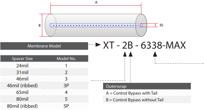
| Item | Description |
| 1 | Permeate Tube |
| 2 | N/A |
| 3 | ATD with Seals |
| 4 | Membrane Body with Hard Shell |
| 5 | ATD |
| 6 | N/A |
| Item | Dimensions |
| A | 40.00” (1016.0mm) |
| B | 7.45” (189.2mm |
| C | N/A |
| D | N/A |
| ID | 1.29” (32.7mm) |
Note: (2) Seals for Systems w/ reverse flow-cleaning capabilities
INSTALLATION PROCEDURES
- Remove the flow meter/assembly from the housing top cap. Store in a safe place to prevent damage.
- Remove the Victaulic coupling from the top cap.
- Lift the top cap off the housing. In most cases the element will lift up with the top cap. If it does not, pull the spent element out by the permeate tube extension, ATD, or by removing the housing and bottom cap to push the element out.
- Carefully remove the element from its storage bag. For elements with rubber seals, ensure they are properly installed by lubricating with glycerine.
- Replace the O-ring on your top cap with the new O-ring supplied with your element and lubricate them with glycerine. A vial of glycerine is included with each shipment.
- Eliminate the residual paint from the housing. Fill the housing approximately 1/3 full with DI/RO water.
- Insert the bottom plug into the end of the element without the rubber seal(s). For elements with no rubber seal, insert bottom plug into any end
- Insert the element into the housing, bottom end plug first. Do not force the element. For elements with tape wrap, you may trim the tape until it has a snug fit.
- Gently push the element to make sure the element is seated on the bottom of the housing. Make sure the permeate tube is completely submerged in DI/RO water.
- Carefully insert the top cap connector into the permeate tube. Replace the Top Cap and tighten the bolts. Reinstallthe flow meter/bypass assembly and tighten the union connections.
- Circulate DI/RO water through the element for 15 minutes in the CIP loop. Purge to drain, and then refill with fresh DI/RO water. If this is not possible, soak the element in DI/RO water for at least one hour, purge to drain, and re-fill the housing with fresh DI/RO water
- Open both the paint permeate to rinse valve and the paint return valve
- Start paint feed pump and slowly open paint feed valve (to fully open in 3-5 minutes). Adjust inlet pressure to a minimum of 50psi.
Warning: When operating on paint or cleaning, the appropriate permeate transport valve must be 100% open. When operating on paint, the “Permeate to Rinse” valve must be 100% open. When cleaning, the “Permeate to CIP tank” valve must be 100% open. Throttling or closing any permeate valve while it’s in operation can cause Leakers and Smokers and will void our Membrane Material & Workmanship warranty. - After the system runs for a few minutes it may be necessary to re-adjust the pressures until the system balances out and the pressure/flow stabilize
RECOMMENDED OPERATING PARAMETERS
| Operating Parameters | |
| Maximum Temperature | 60°C (140°F) |
| pH Range @ Max Temperature | 2-10 |
| pH Range @ Ambient Temperature | 2-10.5 |
| Pressure | PSI | Bar |
| Max Inlet Pressure | 120 | 8.3 |
| Min Outlet Pressure | 10 | 0.7 |
| Max Differential Pressure per Element | 18 | 1.2 |
| Max Permeate Backpressure | 5 | 0.3 |
Note: Soft start on boost pumps required to rninimize pressure/flow shocks to elements.
| Changing Parameters | |
| Maximum Temperature (Short term <30min) | 85°C (185°F) |
| pH Range @ Max Temperature | 2-11 |
| pH Range @ Ambient Temperature | 2-12.5 |
| Chlorine | Norm PPM | Max PPM |
| Free Chlorine During Operation | 0 | <0.1 |
| Chlorine During CIP at pH10.8-11.0 and 50°C | 150 | 180 |
Note: Maximum chlorine exposure for all elements is 30 minutes per day at pH and temperature conditions listed above.
| Dairy Product Total Solids Limits | Feed Spacer (in mils)
|
|||||||
| Sweet Whey Max. T.S. | 15 | 25 | 28 | 30 | ||||
| Acid Whey Max. T.S. | 15 | 24 | 26 | 28 | ||||
| Skim Milk Max. T.S. | 14 | 24 | 26 | 28 | ||||
| Whole Milk Max. T.S. | 15 | 30 | 33 | 35 | ||||
Note: Trials should be made to determine temperature and viscosity effects.
Element Dimensions
| Element | Model No. | Diameter (B) in | Length (A) in | P.W.T. ID |
| 1.8" | 1812F | 1.8 | 12 | 0.63 |
| 2.5" | 2519 2540F 2540M* |
2.5 2.5 2.5 |
19.25 40 38 |
0.63 0.63 0.75 |
| 3.8" | 3838 3838.75 3850 3938.75 |
3.8 3.8 3.8 4.0 |
38 38.75 50 38.75 |
0.83 0.83 0.83 0.63 |
| 4.3" | 4333 4335 4335.5 4336 4338 |
4.3 4.3 4.3 4.3 4.3 |
33 35 35.5 36 38 |
0.83 0.83 0.83 0.83 0.83 |
| 5.8" | 5838 | 5.8 | 38 | 1.14 |
| 6.3" | 6338 6324 |
6.3 6.3 |
38 24 |
1.14 1.14 |
| 6.4" | 6438 6424 |
6.4 6.4 |
38 24 |
1.14 1.14 |
| 7.8" | 7838 7824 |
7.8 7.8 |
38 24 |
1.14 1.14 |
| 8" | 8038 8040 8238 8240 8338 8340 |
8.0 8.0 8.2 8.2 8.3 8.3 |
38 40 38 40 38 40 |
1.14 1.14 1.14 1.14 1.14 1.14 |
| 9.8" | 9838 | 9.8 | 38 | 1.14 |
| 10" | 10338 | 10.3 | 38 | 1.14 |
*1″ permeate tube extensions (0.75″ OD)
Recommended Element Cross Flow Rate
| Element | Feed Spacer (in miles)
|
||||||||||
| 1.8" | m3/hr gpm |
1 4 |
1 5 |
1 6 |
2 7 |
2 7 |
|||||
| 2.5" | m3/hr gpm |
2 9 |
2 10 |
3 11 |
3 12 |
3 13 |
|||||
| 3.8" | m3/hr gpm |
5 22 |
6 25 |
7 29 |
8 33 |
8 35 |
|||||
| 4.3" | m3/hr gpm |
6 29 |
7 32 |
9 38 |
10 44 |
10 46 |
|||||
| 5.8" | m3/hr gpm |
12 51 |
13 59 |
16 69 |
18 78 |
19 83 |
|||||
| 6.3" | m3/hr gpm |
15 65 |
17 74 |
20 88 |
22 99 |
24 105 |
|||||
| 8" | m3/hr gpm |
21 94 |
24 107 |
29 128 |
33 143 |
35 154 |
|||||
| 10" | m3/hr gpm |
42 184 |
48 213 |
57 250 |
64 283 |
68 299 |
|||||
The recommended cross flow rate will be subject to differential pressure limitations and specific applications. Please consult Synder Filtration if additional information is needed.
Membrane Area(SQ. FT.)
| Element | Model No. | Feed Spacer (in mils)
|
|||||||||
| 1.8" | 1812F | N/A | 3.6 | N/A | N/A | N/A | |||||
| 2.5" | 2519 2540F 2540M |
15 34 35 |
13 29 30 |
10 22 23 |
N/A N/A N/A |
N/A N/A N/A |
|||||
| 3.8" | 3838 3838.75 3850 3938.75 |
85 86 100 102 |
72 74 84 89 |
85 59 70 69 |
46 47 52 53 |
38 39 46 47 |
|||||
| 4.3" | 4333 4335 4335.5 4336 4338 |
99 105 107 108 115 |
86 91 93 94 100 |
66 71 72 73 77 |
53 56 57 58 62 |
44 47 48 49 52 |
|||||
| 5.8" | 5838 | 210 | 184 | 147 | 114 | 96 | |||||
| 6.3" | 6338 6324 |
150 245 |
134 220 |
107 176 |
83 136 |
70 115 |
|||||
| 6.4" | 6438 6424 |
157 258 |
140 230 |
112 184 |
83 136 |
74 122 |
|||||
| 7.8" | 7838 7824 |
242 396 |
210 344 |
166 273 |
132 216 |
110 180 |
|||||
| 8" | 8038 8040 8238 8240 8338 8340 |
414 414 441 441 450 450 |
368 368 384 384 400 400 |
287 287 302 302 311 311 |
225 225 238 238 245 245 |
189 189 201 201 207 207 |
|||||
| 9.8" | 9838 | N/A | 564 | 440 | 351 | 296 | |||||
| 10" | 10338 | N/A | 620 | 492 | 386 | 326 | |||||
TECHNICAL NOTES
For element sires not listed, please coil or email Synder Filtration for Moils. We can design on element to fit your exact needs -just specify the element outer diameter (OD) or vessel/housing inner diameter OD), element inner diameter OD, and length. Elements ore also available with or without a controlled bypass tall Additional feed spacers are also available. Trials should be conducted to determine optimal application.
Element Descriptions
| Model No. | OD (in.) | L (in.) | ID* (in.) | Weight (lb) | Weight (kg) |
| 1812F | 1.8 | 12 | 0.63 | 1.0 | 0.5 |
| 2519 2540F 2540M* |
2.5 2.5 2.5 |
19.25 40 38 |
0.63 0.63 0.75 |
2 4 4 |
0.9 1.8 1.8 |
| 3838 3838.75 3850 3938.75 |
3.8 3.8 3.8 4.0 |
38 38.75 50 38.75 |
0.83 0.83 0.83 0.63 |
10 10 13 10 |
4.5 4.5 5.9 4.5 |
| 4333 4335 4335.5 4336 4338 |
4.3 4.3 4.3 4.3 4.3 |
33 35 35.5 36 38 |
0.83 0.83 0.83 0.83 0.83 |
11 11 11 11 12 |
5.0 5.2 5.2 5.2 5.4 |
| 5838 | 5.8 | 38 | 1.14 | 15 | 7 |
| 6338 6324 6438 6424 |
6.3 6.3 6.4 6.4 |
38 24 38 24 |
1.14 1.14 1.14 1.14 |
16 17 29 18 |
7 7.7 13.2 8.2 |
| 7838 7824 |
7.8 7.8 |
38 24 |
1.14 1.14 |
40 26 |
18.2 11.8 |
| 8038 8040 8238 8240 8338 8340 |
8.0 8.0 8.2 8.2 8.3 8.3 |
38 40 38 40 38 40 |
1.14 1.14 1.14 1.14 1.14 1.14 |
38 39 38 40 40 40 |
17.2 17.7 17.2 18 18 18 |
| 9838 | 9.8 | 38 | 1.14 | 42 | 19.1 |
| 10338 | 10.3 | 38 | 1.14 | 50 | 22.7 |
*1″ permeate tube extensions (0.75″ OD)
Note: Different diameters are available. Please specify your requirements when ordering. Specifications are subject to change without notice.
Applications
Similar Membranes
questions? Fill out this form. We’ll contact you within 24 hours!
Resources
MEMBRANE RESOURCES
- Definition of a Membrane
- Membrane Materials: Organic vs. Inorganic
- Pressure-Driven Membrane Filtration Processes
- Concentration Polarization in Pressure-Driven Processes
- Degrees of Membrane Separation
- Flux Behavior in Membrane Processes
Module Configurations & Processes
-> View all membrane resourcesTUTORIALS