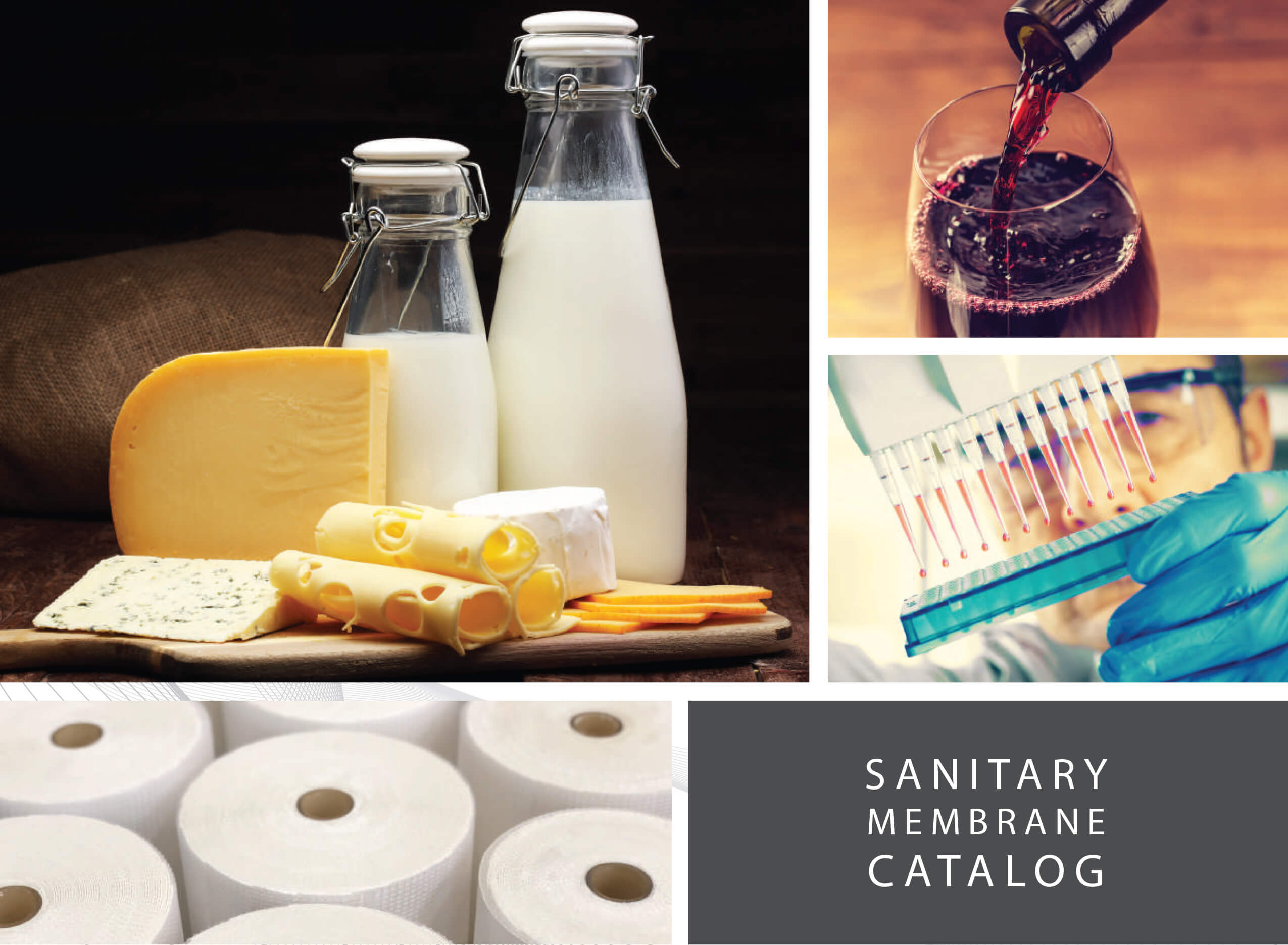
![]() SANITARY MEMBRANE CATALOG
SANITARY MEMBRANE CATALOG
Sanitary Catalog 2024
Company Profile
OUR MISSION
Make the world’s best membrane filters to solve the separation challenges of today, and innovate the membrane technology of the future.
We are guided by these simple rules:
– WORK HARD and ENJOY the process
– INNOVATE to meet our customers’ needs
– TREAT OTHERS as you expect to be treated.
– Be RESPONSIVE
– Be HUMBLE
OUR COMPANY
<
Synder Filtration specializes in manufacturing Nanofiltration, Ultrafiltration, and Microfiltration membranes and systems for specialty process applications. Synder Filtration has a unique understanding of the membrane industry from its history as both a buyer and a supplier of membrane technology. Established in 1989, Synder Inc. originally focused on industrial enzyme technology, and was a pioneer in the application of spiral membranes.
Today, the company serves a variety of industries including dairy, biotech, pharmaceutical, automotive, and oil & gas. All sanitary products meet USDA, FDA and 3-A sanitary standards and Synder is a certified Halal, Kosher, and ISO-9001:2015 manufacturing company.
Synder Filtration is a proud recipient of the President’s "E" Award in recognition of manufacturing export growth. Synder has developed an extensive team of international representatives and distributors with a similar dedication to customer service and deep technical knowledge.
OUR COMMITMENT
With our deep understanding of membrane technology, industry-leading delivery times, and a highly responsive staff, we are dedicated to meeting and exceeding your expectations by doing business "the right way", every single day.
We sincerely look forward to working with you.
Best Regards,
Contents
Applications Overview
The Synder Difference
Degrees of Separation
Nanofiltration Membrane Elements
Ultrafiltration/Microfiltration Membrane Elements
High pH/Temperature UF/MF Membrane Elements
Membrane Technology
SELECTIVE TRANSPORT
Synder Filtration’s polymeric membranes are used to separate, concentrate, and/or fractionate a wide variety of liquids. Membranes serve as a thin barrier between miscible fluids that allow for preferential transport of one or more feed components when a driving force is applied, such as a pressure differential.
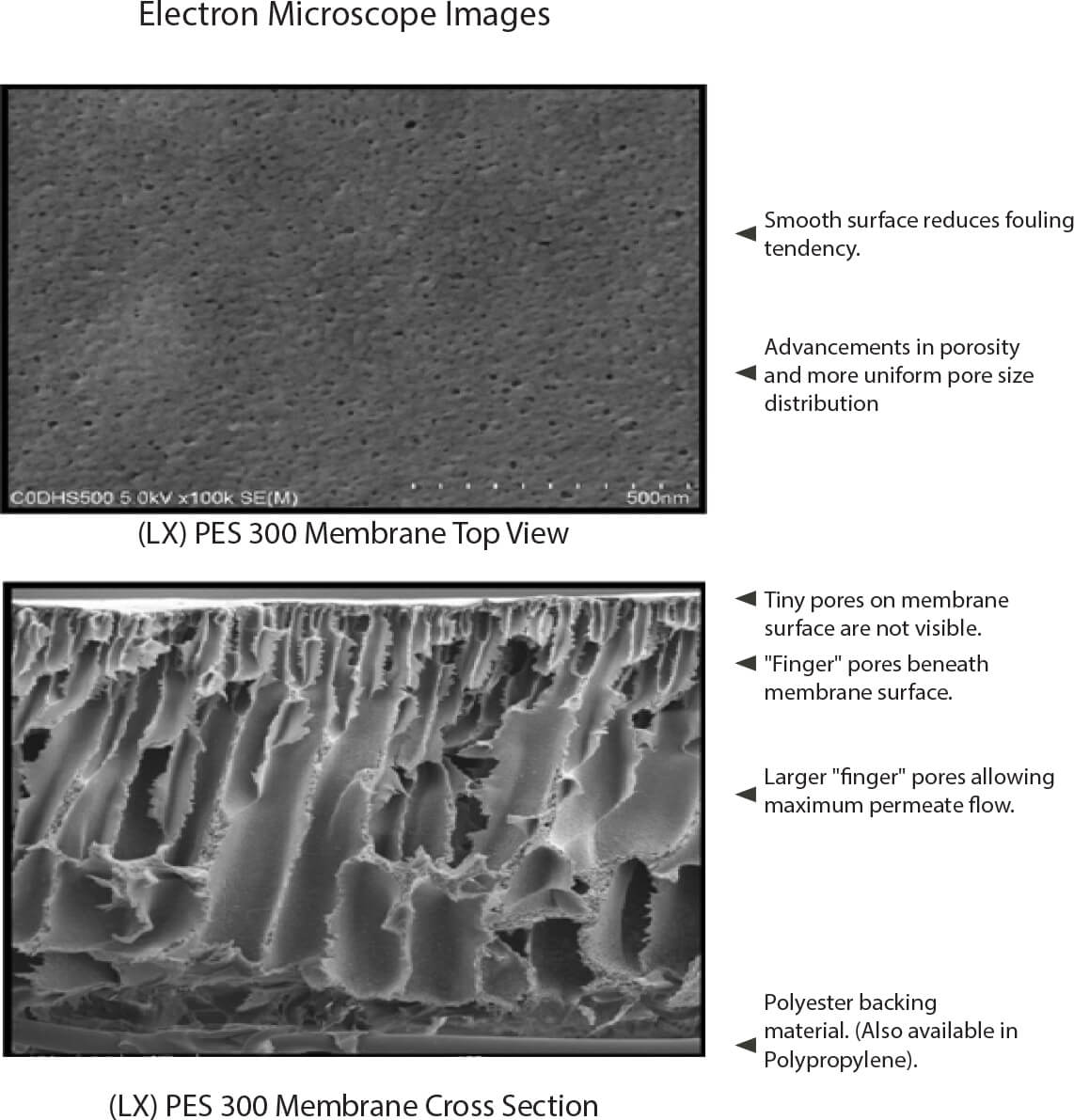
ASYMMETRIC PORE STRUCTURE
Synder membranes feature an asymmetric pore structure. Small surface pores control rejection of target molecules while large “finger pores” beneath the membrane surface allow permeate to move quickly through to a more open permeate carrier. This combination, along with membrane thickness offers an optimal combination of selectivity and permeate flux.
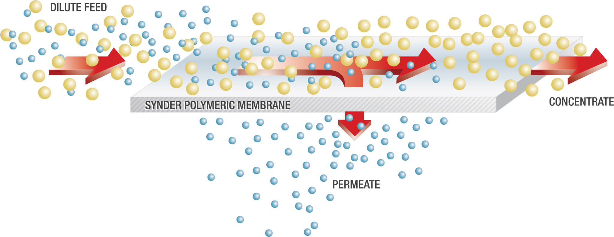
CROSS FLOW PROCESS
Spiral wound membrane elements are fed tangentially. When sufficient pressure or concentration differentials exist on the surface of the membrane, molecules smaller than the surface pores will be driven through it. This solution that passes through the membrane is called the permeate; while the solution rejected by the membrane is called the concentrate (or retentate).
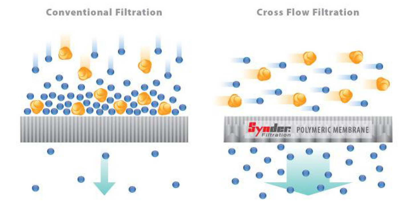
CONVENTIONAL V. CROSS FLOW
Synder’s spiral wound membranes are designed for cross flow (or tangential flow) filtration, where the feed stream runs parallel to the membrane surface. Unlike conventional filtration where solids and solutes immediately accumulate on the membrane surface, cross flow creates a sweeping (or sheering) force along the surface of the membrane to provide for longer filter life and less frequent cleaning cycles, under normal operating conditions.
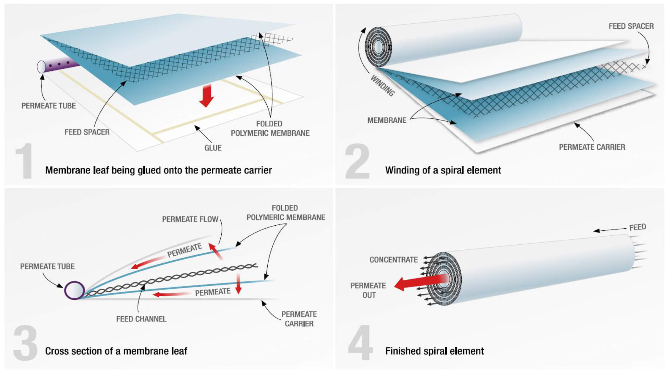
SPIRAL WOUND ELEMENT: A DISSECTION
Forging New Applications & Optimizing Existing Ones

Finding Solutions With Membrane Technology
With over 20 years of application knowledge and experience, Synder Filtration is committed to creating value with membrane technology. In addition to our most common applications listed below, Synder’s process engineers have a deep understanding of how to evaluate new applications efficiently and effectively. Stocking a fleet of pilot systems for all types and sizes of pilot studies, Synder Filtration is ready to help you develop your process.
DAIRY INDUSTRY
Synder has been serving the dairy industry since 1994 and has become a leading supplier worldwide for this application.
| RECOMMENDED MEMBRANES | VT (3kD), MT (5kD), ST (10kD), NFG (600-800) |
Lactose Concentration & Demineralization
Synder’s membranes offer an optimal combination of lactose yield, flux, and demineralization of UF permeate or whey.
| RECOMMENDED MEMBRANES | NFS (100-250Da), NFX (150-300Da) |
Synder originally developed this membrane specifically for milk protein concentration in 1999. Today, it’s used in dairies worldwide.
| RECOMMENDED MEMBRANES | SM (20kD), MK (30kD), MQ (50kD) |
Casein/Whey Fractionation
Synder’s membranes can separate these high value proteins with incredible efficiency.
| RECOMMENDED MEMBRANES | FR (800kD), V0.1 (0.1μm) |
Microfiltration membranes are used for fat and microbial removal in the production of high purity WPC & WPIs. Users typically experience significant cost savings in both CAPEX and OPEX vs. ceramic membranes.
| RECOMMENDED MEMBRANES | FR (800kD) |
Brine Clarification
Ultrafiltration membranes are proven to economically clarify and recover the brine used in the curing of cheese.
| RECOMMENDED MEMBRANES | BN (50kD) |
High pH & Temperature Feed Solutions
Membrane sanitization without the use of chlorine is now a reality.
| RECOMMENDED MEMBRANES | UF/MF MAX |
BIOTECH & PHARMACEUTICAL
Enzyme Concentration
UF and MF membranes are the standard for enzyme concentration and clarification/removal of cell bodies, respectively.
| RECOMMENDED MEMBRANES | MT (5kD), ST (10kD), FR (800kD), V0.1 (0.1μm) |
Antibiotics Production
NF membranes can be used to process a wide range of antibiotics with consistent product purity and performance.
| RECOMMENDED MEMBRANES | NFX (150-300Da) |
Blood Serum
Synder’s Nanofiltration membranes are capable of capturing fibrinogen and other clotting compounds with excellent efficiency.
| RECOMMENDED MEMBRANES | NFX (150-300Da) |
Endotoxin & Pyrogen Removal
Synder UF and MF membranes can efficiently remove endotoxins, pyrogens, microbes, and bacteria.
| RECOMMENDED MEMBRANES | MT (5kD), ST (10kD), V0.1 (0.1μm) |
Polypeptide Concentration
NF membranes can concentrate and purify polypeptides while providing outstanding quality and consistency in operation.
| RECOMMENDED MEMBRANES | NFW (300-500Da), NFG (600-800Da), XT (1kD) |
Common Applications
FOOD & BEVERAGE
Corn Wet Milling
Membranes ranging from MF to NF are commonly used in the wet milling of corn. Numerous applications range from the removal of microorganisms to the concentration and clarification of corn syrup, just to name a few.
| RECOMMENDED MEMBRANES | NFX (150-300Da), NFW (300-500Da), LX (300kD), FR (800kD), V0.1 (0.1μ) |
Gelatin Concentration
Synder’s Ultra & Microfiltration membranes provide optimal retention rates for concentrating gelatin while removing unwanted microorganisms.
| RECOMMENDED MEMBRANES | MT (5kD), ST (10kD) |
Juice Processing
Synder’s Ultra and Nanofiltration membranes consistently display excellent removal of starch, pectin, proteins, and polyphenolic compounds. Microfiltration can also be utilized for the removal of microorganisms.
| RECOMMENDED MEMBRANES | NFX (150-300Da), MT (5kD), ST (10kD), FR (800kD), V0.1 (0.1μm) |
Natural Polymers & Xanthan Gum
Synder’s MF and NF membranes provide an optimal combination of retention rates and throughput required for commercial production while removing harmful
microorganisms.
| RECOMMENDED MEMBRANES | V0.1 (0.1μm), NFX (150-300Da) |
Dealcoholization
NF membranes can remove alcohol efficiently with minimal effect to flavor profile.
| RECOMMENDED MEMBRANES | NFX (150-300Da), NFW (300-500Da) |
Maple Syrup
Concentrating maple sap with spiral wound membranes can reduce overall processing time and operating costs.
| RECOMMENDED MEMBRANES | NFX (150-300Da) |
The Synder Difference
INDUSTRY LEADING SHIPPING TIMES
As a family-owned and financially independent company, we can afford to hold higher inventory levels and ship orders as quickly as possible. Synder Filtration constantly invests in large and diverse inventories of the most common membrane element models and sizes. This inventory matched with a global distribution network allows Synder to get you what you need, when you need it.
PERSONAL RESPONSE POLICY
Synder Filtration has a company-wide policy of personally responding to every customer inquiry within 24 hours. Whether your company employs 10 people or 10,000 people, we offer the same responsiveness and expertise that you’ve come to expect from your most preferred vendors.
CUSTOM ELEMENTS & PRODUCT DEVELOPMENT
We have developed one of the widest ranges of Ultrafiltration membrane molecular weight cutoffs of any manufacturer in the world. Our product line continues to evolve with the needs of our customers. With a highly flexible production strategy, we can alter our manufacturing schedule to incorporate rush orders of the most uncommon models and sizes.
QUALITY POLICY
 At Synder, we believe quality is rooted in the overall customer experience, from the initial inquiry all the way through final technical support and maintenance. Synder is proud to be ISO-9001:2015 certified. We pride ourselves in delivering a premium product and meeting the specific application needs of our customers.
Degrees of Separation
Nanofiltration Membrane Elements
Synder Filtration’s Nanofiltration membranes are engineered and
designed to provide superior separation performance for various
application needs. Delivering stable flux and wide range of rejection
to monovalent and divalent ions, Synder’s NF membranes have been
developed specifically for specialty process applications.
MEMBRANE TYPES
| Model | Polymer | Approx. Molecular Weight Cutoff |
Typical Operating Flux |
Average Lactose Rejection1 |
Average MgSO4 Rejection2 |
Average NaCl Rejection3 |
| NFS | Proprietary PA TFC | 100-250Da | 30-40 GFD | 99.5% | 99.5% | 50.0% |
| NFX | Proprietary PA TFC | 150-300Da | 20-25 GFD | 99.0% | 99.0% | 40.0% |
| NFW | Proprietary PA TFC | 300-500Da | 45-50 GFD | 98.5% | 97.0% | 20.0% |
| NFG | Proprietary PA TFC | 600-800Da | 55-60 GFD | 60.0% | 50.0% | 10.0% |
1Test Conditions 2% Lactose Solution at 110PSI (7.6 Bar) operating pressure, 77° F (25°C)
2Test Conditions 2,000ppm MgSO4 Solution at 110PSI (7.6 Bar) operating pressure, 77° F (25°C)
3Test Conditions 2,000ppm NaCl Solution at 110PSI (7.6 Bar) operating pressure, 77° F (25°C)
WHY SYNDER NF MEMBRANES?
- Optimized flux and rejection
- Operate at lower pressures than Reverse Osmosis membranes and still achieve excellent rejection of polyvalent ions
- Greatly reduce levels of hardness, nitrates, sulfates, tannins, turbidity, color, TDS, and moderate levels of salt from feed streams
CUSTOMIZATION WITH EXCEPTIONAL SPEED
Synder typically stocks the most common models for each membrane, however elements can be customized and delivered with unparalleled lead times.
element made to your exact specifications:
- Element Outer Diameter/Housing Inner Diameter
- Permeate Tube Diameter
- Element Length
DAIRY PRODUCTS TOTAL SOLIDS LIMITS
| Dairy Product Total Solids Limits | Spacer | |||
| Products | 31 | 46 | 65 | 80 |
| Sweet Whey Max. T.S. | 15 | 25 | 28 | 30 |
| Acid Whey Max. T.S. | 15 | 24 | 26 | 28 |
| Skim Milk Max. T.S. | 14 | 24 | 26 | 28 |
| Whole Milk Max. T.S. | 15 | 30 | 33 | 35 |
SANITARY ELEMENT OPERATING SPECIFICATIONS
| Pressure | PSI | Bar |
| Max. Operating Pressure if T<95°F (35°C) | 600 | 41.4 |
| Max. Operating Pressure if T>95°F (35°C) | 435 | 30.0 |
| Max. Pressure Drop per Element | 15 |
1.0 |
| Max. Pressure Drop per Housing | 60 | 4.1 |
| Temperature | Fahrenheit | Celsius |
| Max. Continuous Operation | 122° | 50° |
| Max. CIP Temperature | 104° | 40° |
| pH Parameters | pH |
| Operating Parameters |
At Max Temp. – NFS/NFX: 3-9.5 NFW/NFG: 4-9 |
| At Ambient Temp. – NFS/NFX: 3-10.5 NFW/NFG: 4-10 |
|
| Cleaning Parameters |
At Max Temp. – NFS/NFX: 2-11 NFW/NFG: 3-10 |
| At Ambient Temp. – NFS/NFX: 2-11 NFW/NFG: 3-10.5 |
Chlorine: Dechlorination recommended
NOTE: Trials should be made to determine temperature and viscosity effects. Ribbed spacers are also available for high solids applications.
NF Spiral-Wound Sanitary Elements
DIMENSIONS & WEIGHT
| Element | Model Number | Diameter (B) in (cm) |
Length (A) in (cm) |
PWT ID/OD in (cm) |
Tube Extension (C) in (cm) |
Dry Weight lb (kg) |
| 1.8" | 1812F | 1.8 (4.6) | 12 (30.5) | 0.625 (1.6) | – | 1.0 (0.5) |
| 2.5” | 2540F | 2.4 (6.1) | 40.0 (101.6) | 0.625 (1.6) | – | 4.0 (1.8) |
| 2540M | 2.4 (6.1) | 40.0 (101.6) | – | 1 (2.5) (Both Ends) | 4.0 (1.8) | |
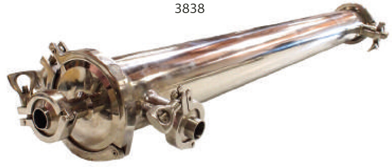
| 3.8” | 3838 | 3.8 (9.7) | 38.0 (96.5) | 0.831 (2.1) | – | 9.0 (4.1) |
| 3838.75 | 3.8 (9.7) | 38.75 (98.4) | 0.831 (2.1) | – | 9.0 (4.1) | |
| 8” | 8038 | 7.9 (20.1) | 38.0 (96.5) | 1.125 (2.9) | – | 29 (13.2) |
| 8040 | 7.9 (20.1) | 40.0 (101.6) | 1.125 (2.9) | – | 29 (13.2) |
RECOMMENDED ELEMENT CROSS FLOW RATE
Feed Spacer (in mils)
| Element | 24 | 31 | 46 | 65 | 80 | |
| 1.8” | m3/hr gpm |
0.7 3 |
0.7 3 |
0.7 3 |
0.9 4 |
0.9 4 |
| 2.5” | m3/hr gpm |
1.4 6 |
1.4 6 |
1.6 7 |
1.6 7 |
1.8 8 |
| 3.8” | m3/hr gpm |
6 26 |
7 29 |
8 33 |
8 36 |
9 38 |
| 8” | m3/hr gpm |
16 68 |
18 76 |
21 89 |
23 98 |
24 103 |
The recommended cross flow rate will be subject to differential pressure limitations and specific applications.
NF MEMBRANE AREAS (SQ FT)
Feed Spacer (in mils)
| Element | 24 | 31 | 46 | 65 | 80 |
| 1812F | 4.7 | 4.0 | 3.0 | 2.3 | 1.9 |
| 2540F | 38 | 30 | 22 | 19 | 15 |
| 2540M | 36 | 28 | 20 | 18 | 14 |
| 3838 | 100 | 87 | 68 | 52 | 43 |
| 3838.75 | 104 | 89 | 69 | 53 | 44 |
| 8038 | 450 | 400 | 300 | 240 | 200 |
| 8040 | 450 | 400 | 300 | 240 | 200 |
TECHNICAL NOTES
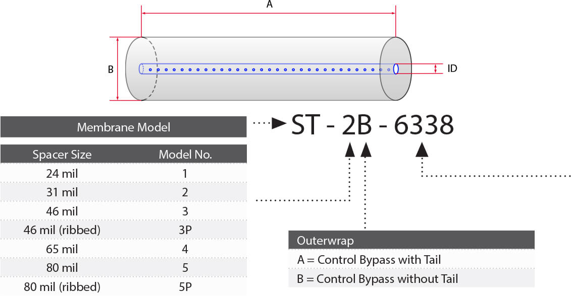
For element sizes not listed, please call or email Synder Filtration for details. We can design an element to fit your exact needs – just specify the element outer diameter (OD) or vessel/housing inner diameter (ID), element inner diameter (ID), and length. Elements are available with or without a controlled bypass tail. Additional feed spacers are also available.
Trials should be conducted to determine optimal application conditions.
Ultrafiltration & Microfiltration Elements
Synder Filtration’s Ultrafiltration and Microfiltration elements
offer an optimal combination of both flux and rejection in a
comprehensive range of MWCOs.
STANDARD SERIES BENEFITS
- Conforms to 3-A, FDA, and USDA sanitary standards
- Wide range of UF MWCO’s available
- Good resistance to pH and temperature
- High resistance to fouling
- Customizable dimensions for unique housings
MEMBRANE MODELS
| MODEL | MWCO | MATERIAL |
| XT | 1,000 | PES |
| VT | 3,000 | PES |
| MT | 5,000 | PES |
| ST | 10,000 | PES |
| SM | 20,000 | PES |
| MK | 30,000 | PES |
| MQ | 50,000 | PES |
| LY | 100,000 | PES |
| LV | 200,000 | PES |
| LX | 300,000 | PES |
| PZ | 30,000 | PAN |
| PY | 100,000 | PAN |
| PX | 400,000 | PAN |
| BN | 50,000 | PVDF |
| BY | 100,000 | PVDF |
| BX | 250,000 | PVDF |
| A6 | 500,000 | PVDF |
| FR | 800,000 | PVDF |
| V0.1 | 0.1 μm | PVDF |
| V0.2 | 0.2 μm | PVDF |
SANITARY ELEMENT OPERATING SPECIFICATIONS
| Pressure | PSI | Bar |
| Max. Inlet Pressure | 120 | 8.3 |
| Min. Outlet Pressure | 10 | 0.7 |
| Max. Differential Pressure per Element | 18 | 1.2 |
| Max. Permeate Backpressure | 5 | 0.3 |
NOTE: Soft start on boost pumps required to minimize pressure/flow shocks to elements.
| Temperature | Fahrenheit | Celsius |
| Max. Operating | 131° | 55° |
| Max. CIP Temperature | 122° | 50° |
| PH Parameters | pH |
| Operating Parameters |
At Max Temp. – PES/PVDF: 3-9 | PAN: 3-10.5 |
| At Ambient Temp. – PES/PVDF: 2-10 | PAN: 3-10 | |
| Cleaning Parameters |
At Max Temp. – PES/PVDF: 2-11 | PAN: 3-10.5 |
| At Ambient Temp. – PES/PVDF: 1.8-11 | PAN: 3-10 |
| Chlorine | Norm. ppm | Max. ppm |
| Free Chlorine in DF Water or Product |
0 | < 0.1 |
| Chlorine during CIP at: pH 10.8-11.0 and 50°C (PES/PVDF) pH 10.5 and 50°C (PAN) |
150 | 180 |
NOTE: Maximum chlorine exposure for all elements is 30 minutes per day at pH and temperature conditions listed above.
| Peroxide | Max. ppm |
| Free Peroxide in Product during Operation | < 3 ppm |
| Peroxide as a Sanitizer at 25°C max, pH 6-7 10 minutes recirculation |
0.1% |
| Dairy Product Total Solids Limits | Spacer (in mils) | |||
| Products | 31 | 46 | 65 | 80 |
| Sweet Whey Max. T.S. | 15 | 25 | 28 | 30 |
| Acid Whey Max. T.S. | 15 | 24 | 26 | 28 |
| Skim Milk Max. T.S. | 14 | 24 | 26 | 28 |
| Whole Milk Max. T.S. | 15 | 30 | 33 | 35 |
NOTE: Trials should be made to determine temperature and viscosity effects. Ribbed spacers are also available for high solids applications.
UF/MF Spiral-Wound Sanitary Elements
ELEMENT DIMENSIONS
| Element | Model Number | Diameter (B) in | Length (A) in | P.W.T. ID |
| 1.8” | 1812F | 1.8 | 12 | 0.63 |
| 2.5” | 2519 2540F 2540M* |
2.5 2.5 2.5 |
19.25 40 38 |
0.63 0.63 0.75* |
| 3.8” | 3838 3838.75 3850 3938.75 |
3.8 3.8 3.8 4.0 |
38 38.75 50 38.75 |
0.83 0.83 0.83 0.63 |
| 4.3” | 4333 4335 4335.5 4336 4338 |
4.3 4.3 4.3 4.3 4.3 |
33 35 35.5 36 38 |
0.83 0.83 0.83 0.83 0.83 |
| 5.8” | 5838 | 5.8 | 38 | 1.14 |
| 6.3” | 6338 6324 |
6.3 6.3 |
38 24 |
1.14 1.14 |
| 6.4” | 6438 6424 |
6.4 6.4 |
38 24 |
1.14 1.14 |
| 7.8” | 7838 7824 |
7.8 7.8 |
38 24 |
1.14 1.14 |
| 8” | 8038 8040 8238 8240 8338 8340 |
8.0 8.0 8.2 8.2 8.3 8.3 |
38 40 38 40 38 40 |
1.14 1.14 1.14 1.14 1.14 1.14 |
| 9" | 9838 | 9.8 | 38 | 1.14 |
| 10” | 10338 | 10.3 | 38 | 1.14 |
*1” permeate tube extensions (0.75” OD)
RECOMMENDED ELEMENT CROSS FLOW RATE
Feed Spacer (in mils)
| Element | 24 | 31 | 46 | 65 | 80 | |
| 1.8” | m3/hr gpm |
1 4 |
1 5 |
1 6 |
2 7 |
2 7 |
| 2.5” | m3/hr gpm |
2 9 |
2 10 |
3 11 |
3 12 |
3 13 |
| 3.8” | m3/hr gpm |
5 22 |
6 25 |
7 29 |
8 33 |
8 35 |
| 4.3” | m3/hr gpm |
6 29 |
7 32 |
9 38 |
10 44 |
10 46 |
| 5.8” | m3/hr gpm |
12 51 |
13 59 |
16 69 |
18 78 |
19 83 |
| 6.3” | m3/hr gpm |
15 65 |
17 74 |
20 88 |
22 99 |
24 105 |
| 8” | m3/hr gpm |
21 94 |
24 107 |
29 128 |
33 143 |
35 154 |
| 10” | m3/hr gpm |
42 184 |
48 213 |
57 250 |
64 283 |
68 299 |
The recommended cross flow rate will be subject to differential pressure limitations and specific applications.
MEMBRANE AREA (SQ. FT.)
Feed Spacer (in mils)
| Element | Model No. | 24 | 31 | 46 | 65 | 80 |
| 1.8" | 1812F | 4.3 | 3.6 | 2.9 | 2.1 | 1.8 |
| 2.5” | 2519 2540M 2540F |
15 34 35 |
13 29 30 |
10 22 23 |
8 17 18 |
7 15 16 |
| 3.8” | 3838 3838.75 3850 3938.75 |
85 86 100 102 |
72 74 84 89 |
58 59 70 69 |
46 47 52 53 |
38 39 46 47 |
| 4.3” | 4333 4335 4335.5 4336 4338 |
99 105 107 108 115 |
86 91 93 94 100 |
66 71 72 73 77 |
53 56 57 58 62 |
44 47 48 49 52 |
| 5.8” | 5838 | 210 | 184 | 147 | 114 | 96 |
| 6.3” | 6324 6338 |
150 246 |
134 220 |
107 176 |
83 136 |
70 115 |
| 6.4” | 6424 6438 |
157 258 |
140 230 |
112 184 |
83 136 |
74 122 |
| 7.8” | 7824 7838 |
242 396 |
210 344 |
166 273 |
132 216 |
110 180 |
| 8” | 8038 8040 8238 8240 8338 8340 |
414 414 441 441 450 450 |
368 368 384 384 400 400 |
287 287 302 302 311 311 |
225 225 238 238 245 245 |
189 189 201 201 207 207 |
| 9" | 9838 | N/A | 564 | 440 | 351 | 296 |
| 10” | 10338 | N/A | 620 | 492 | 386 | 326 |
TECHNICAL NOTES
For element sizes not listed, please call or e-mail Synder Filtration for details. We can design an element to fit your exact needs – just specify the element outer diameter (OD) or vessel/housing inner diameter (ID), permeate tube inner diameter (ID), or outer diameter (OD), and length. Additional feed spacers are also available.
Element Descriptions
| Model No. | OD (in.) | L (in.) | ID* (in.) | Weight (lb) | Weight (kg) |
| 1812F | 1.8 | 12 | 0.63 | 1 | 0.5 |
| 2519 | 2.5 | 19.25 | 0.63 | 2 | 0.9 |
| 2540F | 2.5 | 40 | 0.63 | 4 | 1.8 |
| 2540M | 2.5 | 38 | 0.75* | 4 | 1.8 |
| 3838 | 3.8 | 38 | 0.83 | 10 | 4.5 |
| 3838.75 | 3.8 | 38.75 | 0.83 | 10 | 4.5 |
| 3850 | 3.8 | 50 | 0.83 | 13 | 5.9 |
| 3938.75 | 4.0 | 38.75 | 0.63 | 10 | 4.5 |
| 4333 | 4.3 | 33 | 0.83 | 11 | 5.0 |
| 4335 | 4.3 | 35 | 0.83 | 11 | 5.2 |
| 4335.5 | 4.3 | 35.5 | 0.83 | 11 | 5.2 |
| 4336 | 4.3 | 36 | 0.83 | 11 | 5.2 |
| 4338 | 4.3 | 38 | 0.83 | 12 | 5.4 |
| 5838 | 5.8 | 38 | 1.14 | 15 | 7 |
| 6338 | 6.3 | 38 | 1.14 | 16 | 7 |
| 6324 | 6.3 | 24 | 1.14 | 17 | 7.7 |
| 6438 | 6.4 | 38 | 1.14 | 29 | 13.2 |
| 6424 | 6.4 | 38 | 1.14 | 18 | 8.2 |
| 7838 | 7.8 | 38 | 1.14 | 40 | 18.2 |
| 7824 | 7.8 | 24 | 1.14 | 26 | 11.8 |
| 8038 | 8.0 | 38 | 1.14 | 38 | 17.2 |
| 8040 | 8.0 | 40 | 1.14 | 39 | 17.7 |
| 8238 | 8.2 | 38 | 1.14 | 38 | 17.2 |
| 8240 | 8.2 | 40 | 1.14 | 40 | 18 |
| 8338 | 8.3 | 38 | 1.14 | 40 | 18 |
| 8340 | 8.3 | 40 | 1.14 | 40 | 18 |
| 9838 | 9.8 | 38 | 1.14 | 42 | 19.1 |
| 10338 | 10.3 | 38 | 1.14 | 50 | 22.7 |
*1” permeate tube extensions (0.75” OD). Specifications are subject to change without notice.
High Temperature / pH (MAX Series)
Synder Filtration’s MAX Series Elements offer exceptional physical and chemical durability, in the same wide range of MWCO’s as our standard UF elements.
MAX SERIES BENEFITS
- Conforms to 3-A, FDA, and USDA sanitary standards
- Hot sanitization eliminates chlorine during CIP
- High resistance to pH and temperature
- High resistance to fouling
- Customizable dimensions for unique housings
MEMBRANE MODELS
| MODEL | MWCO | MATERIAL |
| XT | 1,000 | PES |
| VT | 3,000 | PES |
| MT | 5,000 | PES |
| ST | 10,000 | PES |
| SM | 20,000 | PES |
| MK | 30,000 | PES |
| MQ | 50,000 | PES |
| LY | 100,000 | PES |
| LV | 200,000 | PES |
| LX | 300,000 | PES |
| BN | 50,000 | PVDF |
| BY | 100,000 | PVDF |
| BX | 250,000 | PVDF |
| A6 | 500,000 | PVDF |
| FR | 800,000 | PVDF |
| V0.1 | 0.1 μm | PVDF |
| V0.2 | 0.2 μm | PVDF |
NOTE: Trials should be made to determine temperature and viscosity effects. Ribbed spacers are also available for high solids applications.
MAX SANITARY ELEMENT OPERATING SPECS
| Pressure | PSI | Bar |
| Max. Inlet Pressure | 120 | 8.3 |
| Min. Outlet Pressure | 10 | 0.7 |
| Max. Differential Pressure per Element | 18 | 1.2 |
| Max. Permeate Backpressure | 5 | 0.3 |
NOTE: Soft start on boost pumps required to minimize pressure/flow shocks to elements.
| Temperature | Fahrenheit | Celsius |
| Max. Operating | 140° | 60° |
| Max. CIP Temperature | 185° | 85° |
| PH Parameters | pH |
| Operating Parameters |
At Max Temp. – PES: 2-10 | PVDF: 3-10 |
| At Ambient Temp. – PES: 2-10.5 | PVDF: 2-10.5 | |
| Cleaning Parameters |
At Max Temp. – PES: 2-11 | PVDF: 2-11 |
| At Ambient Temp. – PES: 2-12.5 | PVDF: 2-12 |
| Chlorine | Norm. ppm | Max. ppm |
| Free Chlorine in DF Water or Product |
0 | < 0.1 |
| Chlorine during CIP at: pH 10.8-11.0 and 50°C (PES/PVDF) |
150 | 180 |
| Peroxide | Max. ppm |
| Free Peroxide in Product during Operation | < 3 ppm |
| Peroxide as a Sanitizer at 25°C max, pH 6-7 10 minutes recirculation |
0.1% |
| Dairy Product Total Solids Limits | Spacer (in mils) | |||
| Products | 31 | 46 | 65 | 80 |
| Sweet Whey Max. T.S. % | 15 | 25 | 28 | 30 |
| Acid Whey Max. T.S. % | 15 | 24 | 26 | 28 |
| Skim Milk Max. T.S. % | 14 | 24 | 26 | 28 |
| Whole Milk Max. T.S. % | 15 | 30 | 33 | 35 |
MAX Spiral-Wound Sanitary Elements
ELEMENT DIMENSIONS
| Element | Model Number | Diameter (B) in | Length (A) in | P.W.T. ID |
| 1.8” | 1812F | 1.8 | 12 | 0.63 |
| 2.5” | 2519 2540F 2540M* |
2.5 2.5 2.5 |
19.25 40 38 |
0.63 0.63 0.75* |
| 3.8” | 3838 3838.75 3850 3938.75 |
3.8 3.8 3.8 4.0 |
38 38.75 50 38.75 |
0.83 0.83 0.83 0.63 |
| 4.3” | 4333 4335 4335.5 4336 4338 |
4.3 4.3 4.3 4.3 4.3 |
33 35 35.5 36 38 |
0.83 0.83 0.83 0.83 0.83 |
| 5.8” | 5838 | 5.8 | 38 | 1.14 |
| 6.3” | 6338 6324 |
6.3 6.3 |
38 24 |
1.14 1.14 |
| 6.4” | 6438 6424 |
6.4 6.4 |
38 24 |
1.14 1.14 |
| 7.8” | 7838 7824 |
7.8 7.8 |
38 24 |
1.14 1.14 |
| 8” | 8038 8040 8238 8240 8338 8340 |
8.0 8.0 8.2 8.2 8.3 8.3 |
38 40 38 40 38 40 |
1.14 1.14 1.14 1.14 1.14 1.14 |
| 9" | 9838 | 9.8 | 38 | 1.14 |
| 10” | 10338 | 10.3 | 38 | 1.14 |
*1” permeate tube extensions (0.75” OD)
RECOMMENDED ELEMENT CROSS FLOW RATE
Feed Spacer (in mils)
| Element | 24 | 31 | 46 | 65 | 80 | |
| 1.8” | m3/hr gpm |
1 4 |
1 5 |
1 6 |
2 7 |
2 7 |
| 2.5” | m3/hr gpm |
2 9 |
2 10 |
3 11 |
3 12 |
3 13 |
| 3.8” | m3/hr gpm |
5 22 |
6 25 |
7 29 |
8 33 |
8 35 |
| 4.3” | m3/hr gpm |
6 29 |
7 32 |
9 38 |
10 44 |
10 46 |
| 5.8” | m3/hr gpm |
12 51 |
13 59 |
16 69 |
18 78 |
19 83 |
| 6.3” | m3/hr gpm |
15 65 |
17 74 |
20 88 |
22 99 |
24 105 |
| 8” | m3/hr gpm |
21 94 |
24 107 |
29 128 |
33 143 |
35 154 |
| 10” | m3/hr gpm |
42 184 |
48 213 |
57 250 |
64 283 |
68 299 |
The recommended cross flow rate will be subject to differential pressure limitations and specific applications.
MEMBRANE AREA (SQ. FT.)
Feed Spacer (in mils)
| Element | Model No. | 24 | 31 | 46 | 65 | 80 |
| 1.8" | 1812F | 4.3 | 3.6 | 2.9 | 2.1 | 1.8 |
| 2.5” | 2519 2540M 2540F |
15 34 35 |
13 29 30 |
10 22 23 |
8 17 18 |
7 15 16 |
| 3.8” | 3838 3838.75 3850 3938.75 |
85 86 100 102 |
72 74 84 89 |
58 59 70 69 |
46 47 52 53 |
38 39 46 47 |
| 4.3” | 4333 4335 4335.5 4336 4338 |
99 105 107 108 115 |
86 91 93 94 100 |
66 71 72 73 77 |
53 56 57 58 62 |
44 47 48 49 52 |
| 5.8” | 5838 | 210 | 184 | 147 | 114 | 96 |
| 6.3” | 6324 6338 |
150 246 |
134 220 |
107 176 |
83 136 |
70 115 |
| 6.4” | 6424 6438 |
157 258 |
140 230 |
112 184 |
83 136 |
74 122 |
| 7.8” | 7824 7838 |
242 396 |
210 344 |
166 273 |
132 216 |
110 180 |
| 8” | 8038 8040 8238 8240 8338 8340 |
414 414 441 441 450 450 |
368 368 384 384 400 400 |
287 287 302 302 311 311 |
225 225 238 238 245 245 |
189 189 201 201 207 207 |
| 9" | 9838 | N/A | 564 | 440 | 351 | 296 |
| 10” | 10338 | N/A | 620 | 492 | 386 | 326 |
TECHNICAL NOTES
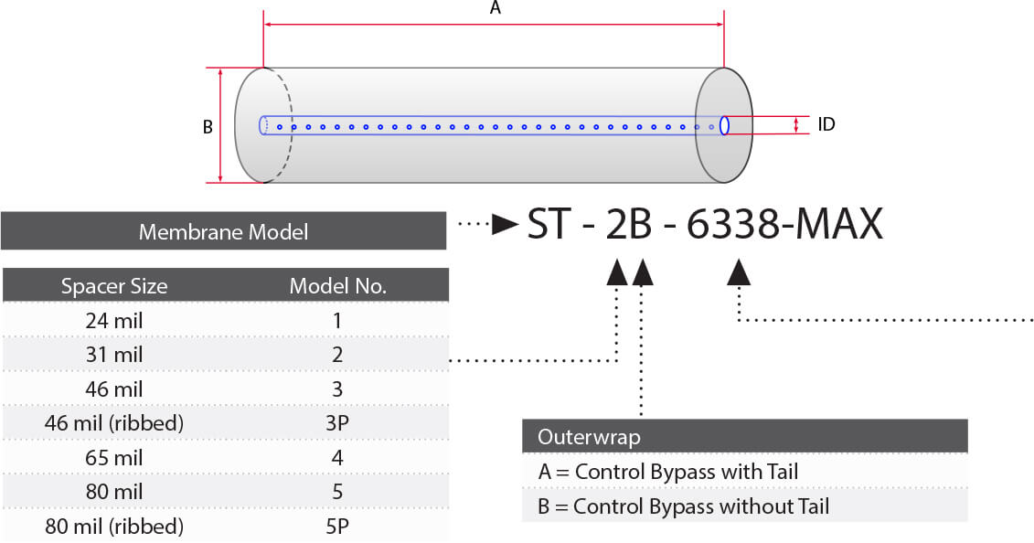
For element sizes not listed, please call or email Synder Filtration for details. We can design an element to fit your exact needs – just specify the element outer diameter (OD) or vessel/housing inner diameter (ID), element inner diameter (ID), and length. Elements
are available with or without a controlled bypass tail. Additional feed spacers are also available. Trials should be conducted to determine optimal application conditions.
Element Descriptions
| Model No. | OD (in.) | L (in.) | ID* (in.) | Weight (lb) | Weight (kg) |
| 1812F | 1.8 | 12 | 0.63 | 1 | 0.5 |
| 2519 | 2.5 | 19.25 | 0.63 | 2 | 0.9 |
| 2540F | 2.5 | 40 | 0.63 | 4 | 1.8 |
| 2540M | 2.5 | 38 | 0.75* | 4 | 1.8 |
| 3838 | 3.8 | 38 | 0.83 | 10 | 4.5 |
| 3838.75 | 3.8 | 38.75 | 0.83 | 10 | 4.5 |
| 3850 | 3.8 | 50 | 0.83 | 13 | 5.9 |
| 3938.75 | 4.0 | 38.75 | 0.63 | 10 | 4.5 |
| 4333 | 4.3 | 33 | 0.83 | 11 | 5.0 |
| 4335 | 4.3 | 35 | 0.83 | 11 | 5.2 |
| 4335.5 | 4.3 | 35.5 | 0.83 | 11 | 5.2 |
| 4336 | 4.3 | 36 | 0.83 | 11 | 5.2 |
| 4338 | 4.3 | 38 | 0.83 | 12 | 5.4 |
| 5838 | 5.8 | 38 | 1.14 | 15 | 7 |
| 6338 | 6.3 | 38 | 1.14 | 16 | 7 |
| 6324 | 6.3 | 24 | 1.14 | 17 | 7.7 |
| 6438 | 6.4 | 38 | 1.14 | 29 | 13.2 |
| 6424 | 6.4 | 38 | 1.14 | 18 | 8.2 |
| 7838 | 7.8 | 38 | 1.14 | 40 | 18.2 |
| 7824 | 7.8 | 24 | 1.14 | 26 | 11.8 |
| 8038 | 8.0 | 38 | 1.14 | 38 | 17.2 |
| 8040 | 8.0 | 40 | 1.14 | 39 | 17.7 |
| 8238 | 8.2 | 38 | 1.14 | 38 | 17.2 |
| 8240 | 8.2 | 40 | 1.14 | 40 | 18 |
| 8338 | 8.3 | 38 | 1.14 | 40 | 18 |
| 8340 | 8.3 | 40 | 1.14 | 40 | 18 |
| 9838 | 9.8 | 38 | 1.14 | 42 | 19.1 |
| 10338 | 10.3 | 38 | 1.14 | 50 | 22.7 |
*1” permeate tube extensions (0.75” OD). Specifications are subject to change without notice.
Flat Sheet Membranes
Synder Filtration offers its complete line of Nanofiltration (NF), Ultrafiltration (UF), and Microfiltration (MF) membranes in a variety of different flat sheet and membrane roll options. With sizes ranging from one square foot to thousands of linear feet, Synder can supply membrane for all scales of testing, research, and production with exceptionally fast lead times.
| Membrane | Type | Polymer | Molecular Weight Cut-Off |
| NFS | NF | TFC | 100-250 |
| NFX | NF | TFC | 150-300 |
| NFW | NF | TFC | 300-500 |
| NFG | NF | TFC | 600-800 |
| XT | UF* | PES | 1,000 |
| VT | UF* | PES | 3,000 |
| MT | UF* | PES | 5,000 |
| ST | UF* | PES | 10,000 |
| SM | UF* | PES | 20,000 |
| MK | UF* | PES | 30,000 |
| MQ | UF* | PES | 50,000 |
| LY | UF* | PES | 100,000 |
| LV | UF* | PES | 200,000 |
| LX | UF* | PES | 300,000 |
| PZ | UF | PAN | 30,000 |
| PY | UF | PAN | 100,000 |
| PX | UF | PAN | 400,000 |
| V3 | UF*1 | PVDF | 30,000 |
| V4 | UF*1 | PVDF | 70,000 |
| V5 | UF*1 | PVDF | 200,000 |
| V6 | UF*1 | PVDF | 500,000 |
| V7 | UF*1 | PVDF | 800,000 |
| BN | UF* | PVDF | 50,000 |
| BY | UF* | PVDF | 100,000 |
| BX | UF* | PVDF | 250,000 |
| A6 | UF* | PVDF | 500,000 |
| FR | MF* | PVDF | 800,000 |
| V0.1 | MF* | PVDF | 0.1μm |
| V0.2 | MF* | PVDF | 0.2μm |
*MAX (High Temperature/High pH) Models Also Available
1Not Approved for Use in Food Contact Applications
MODEL INFORMATION
| Size | Wet/Dry | Notes |
| 12” x 12” | Both Available | Custom Sizes / Shapes Available |
| 1m x 1m | Both Available | Custom Sizes / Shapes Available |
| Dry Roll | Dry Only | 800 Linear Foot Minimum |
Membrane Accessories & Spare Parts
Synder Filtration stocks large inventories of the accessories and spare parts required for membrane installation and operation. With a wide range of Anti-Telescoping Devices (ATDs) and lip seals to fit all of our sanitary membranes, Synder can supply or replace these accessories with exceptional speed to help prevent delays in production or pilot testing. We can also provide full sanitary grade housings for our elements, which can be customized to fit any system. Contact us to find the most appropriate ATD, lip seal, or housings for your process.
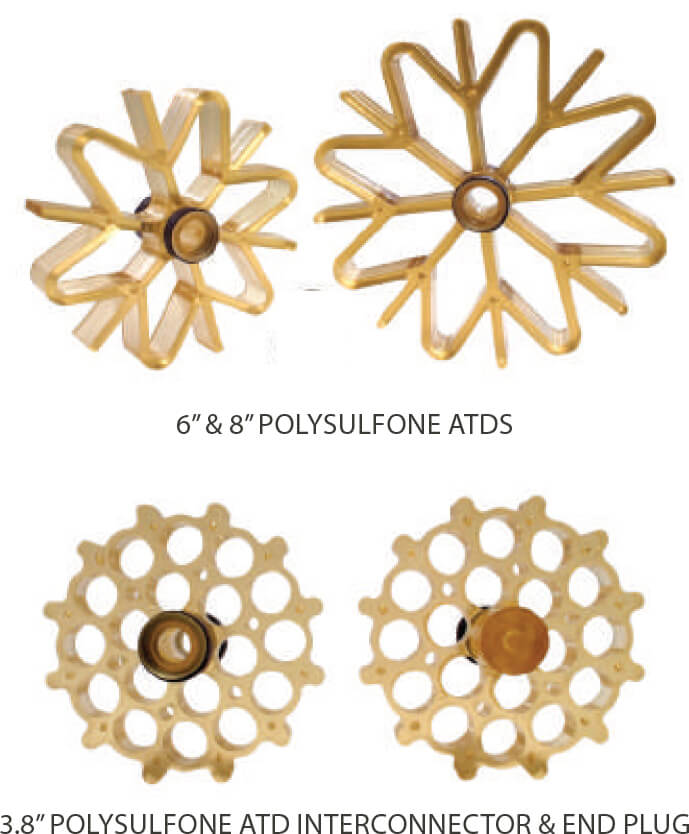
ANTI-TELESCOPING DEVICES (ATDs)
| Size | Configuration |
| 3.8” | ATD Interconnector |
| 3.8” | ATD End Plug |
| 6.3” | ATD Interconnector |
| 6.3/8.0" | ABS End Plug |
| 8.0” | ATD Interconnector |
| 8.0" | 8040 Interconnector |
| Materials | Features |
| Polysulfone | Industry Standard, Chemically Robust |
| Stainless Steel 304 | Designed For High Temp / High Pressure Feed Solutions |
*Contact Synder for custom sizes.
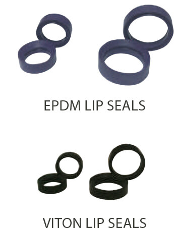
LIP SEALS
| Size | Corresponding Element OD | Available Materials |
| 0.831” | 3.8”, 4.3” | EPDM, Viton |
| 1.138” | 6.3”, 8.0” | EPDM, VIton |
| Materials | Features |
| EPDM | Industry Standard |
| Viton | Greater Chemical, Temperature, Solvent Resistivity |
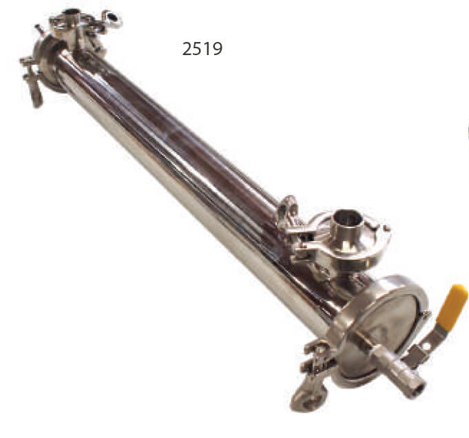
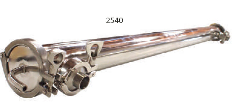
SANITARY GRADE HOUSINGS
| Model | Corresponding Element | Available Materials |
| 2519 | UF/MF/NF 2519 | Stainless Steel 304 & Tri-Clamp Fittings |
| 2540 | UF/MF/NF 2540 | Stainless Steel 304 & Tri-Clamp Fittings |
| 3838 | UF/MF/NF 3838 | Stainless Steel 304 & Tri-Clamp Fittings |
*Contact Synder for additional sizes.
Element Installation Procedures
Outerwrap “Without Tail”
Spiral elements must fit snugly in their vessels in order for them to function properly. If a loose-fitting element is put into operation, one of two unfavorable consequences may result:
a) Too much liquid will by-pass the element, going around rather than through it. This can result in lower fluxes, more rapid membrane fouling, lower permeate flow, longer cleaning times, and increased costs of cleaning chemicals.
b) A loose-fitting spiral element may lose some physical integrity by expanding to fit the housing. This can result in buckling, wrinkling, and/or channeling which may cause a premature leakage of the membrane.
A preservative solution is used to prevent microbial growth and membrane dry-out during shipping and storage. While this solution is not classified as hazardous, extra care should be take to limit exposure. The elements should undergo a standard cleaning (CIP) procedure prior to start up to ensure that preservative has been fully rinsed, and that final rinse water is at a neutral pH.
Recommended Equipment: Sharp knife or scissors, gloves, safety glasses, and dust mask.
Installation Procedures
- Remove the element from the plastic bag and take this opportunity to do a thorough visual examination of the element. There should be
no mold, dust, or dirt anywhere on the element. If preservative fumes are uncomfortable for some, allow bags to air out for 30-60 minutes
after opening. - Prepare an element loading diagram to document the serial number(s), date, element model number, location within the system, and any
other required information for future reference. - Attempt to install the element into the pressure vessel. It should fit snugly. Be sure to examine Anti-Telescoping Devices (ATDs) and lip
seals and replace if needed. - Lip seals should be well lubricated prior to installation with a non-petroleum based lubricant such as glycerine or any mild household
liquid detergent. Inserting the ATD with lip seals should be done with a slow twisting motion to ensure a good seal and to prevent leakage. - A sufficient flush should be performed on all elements prior to start-up. Clean water at 122°F (50°C) should be used in a non-recirculating
mode for at least 10 minutes after installation. This should remove all preservative solutions, glycerine, etc. and will help ensure successful
membrane performance. The element should be at a neutral pH and thoroughly flushed prior to start-up. Additionally, a caustic wash is
recommended as well prior to start-up. For UF/MF a 30min rinse and 120-125°F (49-52°C) is sufficient, while NF is recommended to have
two caustic washes (15min each) at 115-118°F (46-48°C) with clean water rinses in between. The element should be at a neutral pH and
thoroughly flushed prior to start-up. See specsheets for pH range limitations. - The element is now ready for start-up. Feed and/or recirculation pumps should “ramp-up” RPMs slowly to prevent the element from being
shocked. Variable Frequency Drives (VFDs) are recommended for all feed and recirculation pumps to safely control pump RPMs. - Synder Filtration requires the collection of daily performance data of the system and element performance. The following data should be collected at least daily, and is required in the event of a warranty claim:
- Flows (feed, permeate, concentrate)
- Pressures (feed, permeate, concentrate)
- Operating temperatures (production and CIP)
- Hours of operation (production and CIP)
- Other cleaning parameters (pH, time, chlorine exposure)
- Unexpected events (system upsets, unscheduled shutdowns, etc.)
Outerwrap “With Tail”
To further improve the fit of the element in the vessel, Synder Filtration offers a “trim-to-fit” outerwrap. The inner diameter can sometimes vary between vessels, and this allows for a customized fit for each vessel.
A preservative solution is used to prevent microbial growth and membrane dry-out during shipping and storage. While this solution is not classified as hazardous, extra care should be take to limit exposure.
Recommended Equipment: Sharp knife or scissors, gloves, safety glasses, and dust mask.
Installation Procedures
- Remove the element from the plastic bag and take this opportunity to do a thorough visual examination of the element. There should be no mold, dust, or dirt anywhere on the element. If preservative fumes are uncomfortable for some, allow bags to air out for 30-60 minutes after opening. Remove the tape strips from the element.
- Prepare an element loading diagram to document the serial number(s), date, element model number, location within the system, and any other required information for future reference.
- Attempt to install the element into the pressure vessel.
- If the element does not fit snugly, trim off the tail from the element at approximately 1/4 of the Outer Diameter (OD) at a time. Test the element’s fit after each trimming. Ideally, the element should fit snugly into the vessel.
- Inspect Anti-Telescoping Devices (ATDs) and lip seals and replace if needed.
- Lip seals should be well lubricated prior to installation with a non-petroleum based lubricant such as glycerine or any mild household liquid detergent. Inserting the ATD with lip seals should be done with a slow twisting motion to ensure a good seal and to prevent leakage.
- A sufficient flush should be performed on all elements prior to start-up. Clean water at 122°F (50°C) should be used in a non-recirculating mode for at least 10 minutes after installation. This should remove all preservative solutions, glycerine, etc. and will help ensure successful membrane performance. The element should be at a neutral pH and thoroughly flushed prior to start-up. Additionally, a caustic wash is recommended as well prior to start-up. For UF/MF a 30min rinse and 120-125°F (49-52°C) is sufficient, while NF is recommended to have two caustic washes (15min each) at 115-118°F (46-48°C) with clean water rinses in between. The element should be at a neutral pH and thoroughly flushed prior to start-up. See specsheets for pH range limitations.
- The element is now ready for start-up. Feed and/or recirculation pumps should “ramp-up” RPMs slowly to prevent the element from being shocked. Variable Frequency Drives (VFD’s) are recommended for all feed and recirculation pumps to safely control pump RPMs.
- Synder Filtration requires the collection of daily performance data of the system and element performance. The following data should be collected at least daily, and is required in the event of a warranty claim:
- Flows (feed, permeate, concentrate)
- Pressures (feed, permeate, concentrate)
- Operating temperatures (production and CIP)
- Hours of operation (production and CIP)
- Other cleaning parameters (pH, time, chlorine exposure)
- Unexpected events (system upsets, unscheduled shutdowns, etc.)
Standard Cleaning Guidelines
The following procedure is a general guideline for the cleaning/sanitization of spiral elements for most food and dairy applications. Depending on individual process streams, equipment and process time some variations in cleaning procedures may be required for optimal cleaning results. Please consult a qualified chemical supplier for application specific cleaning regimes.
Improper cleaning sequence, chemical concentration or abnormal temperatures/pH/pressure profiles can significantly reduce membrane life and possibly void any warranties offered on the element(s). If you have any questions or concerns about your cleaning regime, please contact Synder Filtration immediately.
Concentrate Displacement and Initial Flush
- Flush the remaining concentrate in the system back to the concentrate tank or to drain.
- Using clean water heated to 122°F/50°C (or 104°F/40°C for NF), adequately flush the system in non-recirculation mode to remove any remaining build-up. The retentate and permeate should appear to be clean after this step.
- Perform a complete Clean-In-Place (CIP) immediately after the initial flush per the following.
Caustic Wash
- Circulate warm clean water (122°F/50°C, or 104°F/40°C for NF) through the system under standard pressure and flow parameters.
- Add caustic SLOWLY to achieve a pH of 10.8-11.0. DO NOT EXCEED pH 11.0 (pH 10.5 for NFW/NFG/PZ/PY/PX).
- Circulate caustic solution for 30 minutes.
- Flush the system to drain with clean, warm water (same temperature as before).
Acid Wash
- Circulate warm clean water through the system under standard pressure and flow parameters.
- Add a sufficient amount of acid SLOWLY to achieve a pH of 2.0-2.2. DO NOT EXCEED pH 2.0 (pH 3.0 for NFW/NFG/PZ/PY/PX).
- Circulate acid solution for 30 minutes.
- Flush the system to drain with clean, warm water (same temperature as before).
Sanitation (Caustic/Chlorine Solution) – FOR UF/MF
- Circulate warm clean water through the system under standard pressure and flow parameters.
- Add caustic SLOWLY to achieve a pH of 10.8-11.0. DO NOT EXCEED pH 11.0 (pH 10.5 for PZ/PY/PX).
- Add chlorine SLOWLY to achieve constant level of 150 ppm. DO NOT EXCEED 180 ppm.
- Circulate the caustic/chlorine solution for 30 minutes.
- Periodically check and maintain a chlorine concentration of 150 ppm.
- Flush the system to drain with clean, warm water (same temperature as before).
Note: For NF, dechlorination is recommended.
Synder Filtration believes the above information and data herein to be accurate. However, said information is offered in good faith, but without guarantee of results since the conditions and methods used are beyond Synder Filtration’s control. Synder Filtration assumes no liability as to the application of the previously mentioned data.
Cleaning Guidelines for High pH/Temperature
The following procedure is a general guideline for the cleaning/sanitization of MAX spiral elements for most food and dairy applications. The cleaning time for MAX elements is typically 2-4 times faster than traditional cleaning procedures.
Depending on individual process streams, equipment and process time some variations in cleaning procedures may be required for optimal cleaning results. Please consult a qualified chemical supplier for application specific cleaning regimes.
Improper cleaning sequence, chemical concentration or abnormal temperatures/pH/pressure profiles can significantly reduce membrane life and possibly void any warranties offered on the element(s). If you have any questions or concerns about your cleaning regime, please contact Synder Filtration immediately.
Concentrate Displacement and Initial Flush
- Flush the remaining concentrate in the system back to the concentrate tank or to drain.
- Using clean water heated to 122°F/50°C, adequately flush the system in non-recirculation mode to remove any remaining build-up. The retentate and permeate should appear to be clean after this step.
- Perform a complete Clean-In-Place (CIP) immediately after the initial flush per the following.
Caustic Wash
- Circulate warm clean water (122°F/50°C) through the system under standard pressure and flow parameters.
- Add caustic SLOWLY and DO NOT EXCEED pH 12.5 for PES and pH 12 for PVDF at ambient temperatures.
- Circulate caustic solution for 10 minutes.
- Flush the system to drain with clean, warm water (same temperature as before).
Acid Wash
- Circulate warm clean water 122°F/50°C through the system under standard pressure and flow parameters.
- Add a sufficient amount of acid SLOWLY to achieve a pH of 2.0-2.2.
- Circulate acid solution for 20 minutes.
High Temperature/pH Sanitation
- Circulate hot clean water 185°F (85°C) through the system under standard pressure and flow parameters.
- Add caustic SLOWLY to achieve a pH of 11. DO NOT EXCEED pH 11.
- Circulate the caustic solution for 10 minutes.
- Flush the system to drain with clean, warm water 122°F/50°C.
Alternative Sanitation Method (Caustic/Chlorine Solution)
Note: This cleaning method can be used in place of the High Temperature/pH Sanitation method mentioned above. Do not combine sanitation methods.
- Circulate warm clean water through the system under standard pressure and flow parameters.
- Add caustic SLOWLY to achieve a pH of 10.8-11.0. DO NOT EXCEED pH 11.
- Add chlorine SLOWLY to achieve constant level of 150 ppm. DO NOT EXCEED 180 ppm.
- Circulate the caustic/chlorine solution for 30 minutes.
- Periodically check and maintain a chlorine concentration of 150 ppm.
- Flush the system to drain with clean, warm water (same temperature as before).
See water quality standards for "clean water" on pg. 20. Synder Filtration believes the above information and data herein to be accurate. However, said information is offered in good faith, but without guarantee of results since the conditions and methods used are beyond Synder Filtration’s control. Synder Filtration assumes no liability as to the application of the previously mentioned data.
Element Storage Procedures
6 Months or Less (Short Term)
Immediately following the final CIP flush, the system should be filled with 1% Sodium Metabisulfite (MBS) solution (0.1% MBS for NF elements) with a pH of 4.0-5.0. Every 7-10 days the following procedure should be performed:
- Drain MBS solution from the system and flush to drain with clean water.
- Run a caustic wash. (See caustic wash directions on p. 17 and 18)
- Flush to drain with clean water.
- Recharge the system with a fresh bath of MBS.
Longer than 6 Months (Long Term)
A long term shutdown (over 6 months) can be handled easily and efficiently. This involves the removal of elements from the system, soaking them in preservative solution (vertically if possible), and sealing in a plastic bag for future use.
The preservative solution should include:
- 20% Glycerine
- 2% Sodium Metabisulfite (0.1% Sodium Metabisulfite for NF elements)
- pH 4.0-5.0
- Remove the element from the vessel, drain the elements in a vertical position to avoid extensive dilution of the preservative solution.
- Place the element in a preservative for a minimum of 15 minutes.
- Remove the element from the preservative and allow it to drain for approximately 10 seconds, then place the element back in the bag.
- Seal the bag either via heat seal or waterproof tape. This should be done well to prevent any leakage during storage/transport.
- Depending on the number of elements, the preservative solution may become diluted. In that event, add more preservative to maintain pH 4.0-5.0.
- Element storage in 50°F – 59°F (10°C – 15°C) will increase storage life of the elements. If refrigeration is possible, it is highly recommended by Synder Filtration.
- Contact Synder Filtration prior to storing any elements to discuss any remaining element warranty.
Synder Filtration believes the above information and data herein to be accurate. However, said information is offered in good faith, but without guarantee of results since the conditions and methods used are beyond our control. Synder Filtration assumes no liability as to the application of the previously mentioned guidelines.
Water Quality Guidelines For CIP
The quality of water used for flushing and cleaning Synder Filtration membranes is of utmost importance in order to avoid unwanted deposits on the membrane originating from the water. In most cases, municipal water does not qualify as “clean water”.
Special attention should be paid to possible foulants such as iron, manganese, and silicates. Clean water must meet the following specifications at all times:
| FOULANT | REQUIREMENT |
| Iron (Fe) | <0.05ppm |
| Manganese (Mn) | <0.02ppm |
| Silicate (SiO2) | <5ppm |
| Aluminum (Al) | <0.05ppm |
| Hardness | <85ppm as CaCO3 |
| Particle Size | <10 micron |
| Turbidity | <1 NTU |
Membrane Customization
At Synder Filtration, we aim to provide quality products, technical expertise, and quick responsiveness. We take pride
in collaborating closely with our customers to ensure consistent membrane performance and complete satisfaction
with each product. Contact us today for more information about our membrane development program.

1. Customer submits membrane development inquiry to Synder Sales
Dept. This helps us to gather vital information about potential usage for the membrane and establish project goals.
2. Inquiry review by R&D and Engineering Team. Synder’s R&D and engineering staff will review the inquiry to assess the overall process goals and feasibility of the project. If approved, they will then put together a proposal for the customer highlighting the
development plan, project timeline, and costs.
3. Customer approval. Once the proposal from R&D is sent to the customer, the account manager will schedule a review meeting or conference call to discuss the project and clarify any remaining questions. After everything is reviewed, the customer will then decide the next action steps for the project.
4. Research & development testing. If the proposal is approved by the customer and the plan is finalized, Synder’s R&D team will work together to start developing potential membranes. For testing, multiple types of analysis can be provided including SEM imaging, FTIR analysis, contact angle measurements, TOC readings, molecular weight cut-off, and pore distribution.
5. Samples sent to customer. Once the analysis is completed, a summary report will be sent to the customer for examination. Lab samples may also be sent for further validation in their process and modifications to the membrane formulations can be made based on feedback from the customer.
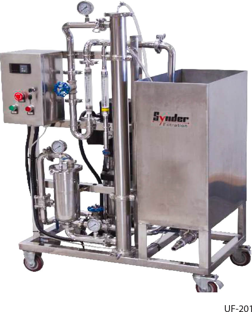
Pilot Study Program
Many new membrane applications require pilot testing during their development phase. Synder offers an extensive pilot study program to help our customers develop innovative applications. As an industry leader in supporting research and development activities, we know the importance of having low cost, flexibility, and quick responsiveness.
Contact us today to learn more about our Pilot Study program. We look forward to serving you.
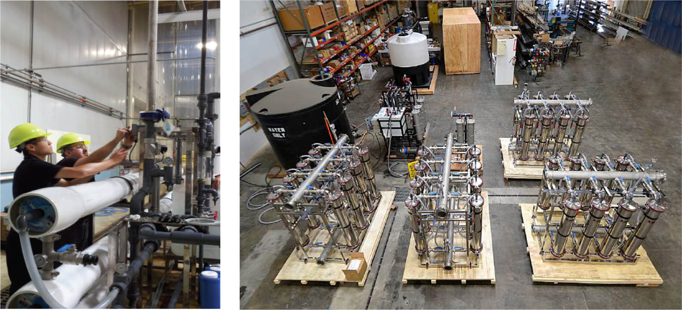
Pilot Studies at Synder’s Laboratories
For the companies that prefer to let Synder’s professionals gauge the feasibility or performance of their application, we run a full range of pilot and feasibility testing at Synder headquarters in Vacaville, CA, USA.
- Flat sheet feasibility tests and performance estimations with both single and eight bank cells which require 5 or 10 liter samples, respectively.
- Complete spiral wound Microfiltration, Ultrafiltration, and Nanofiltration pilot studies, done in-house for extended performance testing.
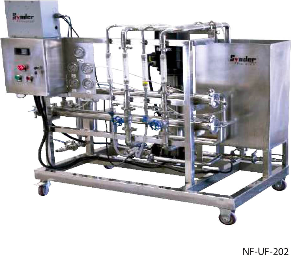
Systems & Application Development
Membrane filtration systems are the heart of many separation processes. Application research, equipment design, and fabrication quality are all critical factors in the ultimate success of a project. To start, the proper membrane configuration must be selected. Although there are many formats to choose from such as plate & frame, hollow fiber, and tubular, spiral-wound membranes are often preferred due to their well-rounded balance of characteristics. Spiral elements feature excellent membrane packing density (unit area per unit volume), physical and chemical resistance, and unit cost. One important requirement of spiral membranes is that the vast majority of suspended solids and particulates must be removed via pre-filtration.
Synder Filtration is an ISO-9001:2015 certified manufacturer of spiral-wound membranes and membrane systems, capable of engineering and fabricating reverse osmosis, nanofiltration, ultrafiltraiton, and microfiltration membrane systems. Controls design and panel assembly are done in-house, giving us the ability to customize and modify process designs quickly and competently.
In addition, Synder offers a full service application development program, aimed at helping our customers research and prove out their separation performance with as much support as required from our experienced technical team. With our newly designed research & development laboratory and fleet of pilot systems, we are able to conduct a wide range of feasibility tests both in-house and on-site. Our unique and collaborative application development program offers great flexibility for further development in specialty process applications.
Feasibility Testing
At Synder Filtration, we take pride in providing technical expertise and personal collaboration with our customers. We strive to gain a better understanding of your process goals in order to develop a comprehensive testing plan designed to suit your separation needs. Our unique and collaborative application development program offers great flexibility for further development in specialty process applications.
1. Pilot Study RFQ Form Submission. This helps us to gather important information about the feed stream, operating parameters, and the customer’s application goals.
2. RFQ review. Synder account manager schedules review meeting with the customer and the engineering staff to discuss the project and clarify any remaining questions.
3. Feasibility testing. A feasibility test is proposed to the customer, and conducted if approval is received. A feasibility report is prepared with 24-48 hours after test completion.
- Flat sheet feasibility tests: Synder’s complete line of NF, UF, and MF and MAX membranes are available in a variety of different flat sheet options for feasibility testing.
- Spiral element feasibility tests: In some cases such as feed streams requiring high operating pressure to obtain additional concentration and flux data, spiral elements may be recommended for use on feasibility tests.
- Analytical capabilities include TOC levels, COD levels, hardness, chloride, sulfate, and iron concentrations, liquid viscosity, turbidity, pH, and conductivity measurements. Synder is also able to outsource other analytical capabilities such as SEM, FTIR, BOD, TSS, and ICP, if the customer accepts 3rd party involvement in the testing.
4. Pilot study testing. If feasibility results are positive, a pilot study is proposed. Pilot studies can last anywhere from
one week to several months or longer, depending on the nature of the application and possible variability in the feed stream. See pilot system specs.
5. Full scale system design & fabrication. If the pilot study results are positive, a full scale system is proposed and revised as needed until the customer is satisfied with the design specs, lead time, and projected ROI. Synder then fabricates the system.
6. System installation & commissioning. The final step is installation, commissioning, and training on site. Start up and commissioning service can be done worldwide.