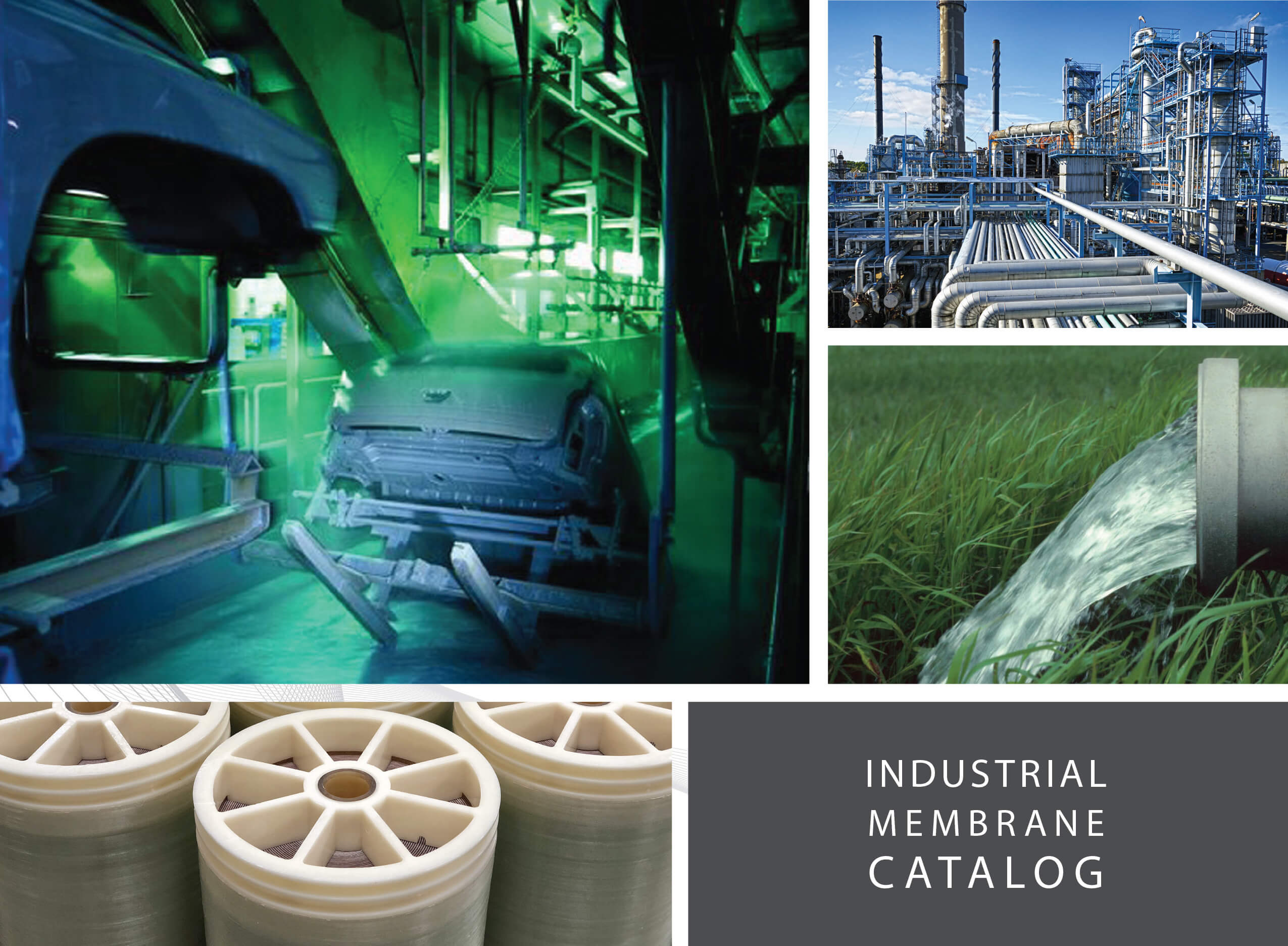
![]() INDUSTRIAL MEMBRANE CATALOG
INDUSTRIAL MEMBRANE CATALOG
Industrial Catalog 2024
Company Profile
OUR MISSION
Make the world’s best membrane filters to solve the separation challenges of today, and innovate the membrane technology of the future.
We are guided by these simple rules:
– WORK HARD and ENJOY the process
– INNOVATE to meet our customers’ needs
– TREAT OTHERS as you expect to be treated.
– Be RESPONSIVE
– Be HUMBLE
OUR COMPANY
Synder Filtration specializes in manufacturing Nanofiltration, Ultrafiltration, and Microfiltration membranes and systems for specialty process applications. Synder Filtration has a unique understanding of the membrane industry from its history as both a buyer and a supplier of membrane technology. Established in 1989, Synder Inc. originally focused on industrial enzyme technology, and was a pioneer in the application of spiral membranes.
Today, the company serves a variety of industries including dairy, biotech, pharmaceutical, automotive, and oil & gas. All sanitary products meet USDA, FDA and 3-A sanitary standards and Synder is a certified Halal, Kosher, and ISO-9001:2015 manufacturing company. Synder Filtration is a proud recipient of the President’s “E” Award in recognition of manufacturing export growth.
Synder has developed an extensive team of international representatives and distributors with a similar dedication to customer service and deep technical knowledge.
OUR COMMITMENT
With our deep understanding of membrane technology, industry-leading delivery times, and a highly responsive staff, we are dedicated to meeting and exceeding your expectations by doing business “the right way”, every single day.
We sincerely look forward to working with you.
Best Regards,

Contents
BACKGROUND
Membrane Technology Overview
E-Coat Process Diagram
Synder Membrane Range
Degrees of Separation
Industrial Applications
The Synder Difference
MEMBRANES/ANODE CELLS
NF Industrial Elements
UF/MF Industrial Elements
UF E-Coat Elements
TechCELL
SuperCELL
SYSTEMS
UF/MF Industrial Systems
NF/RO Industrial Systems
Sanitary Systems
Anode Cell CMS
EDUF Systems
Anolyte Recirculation System
Pilot Study Program
Custom Units
Engineering Services
CASE STUDIES
Seawater Sulfate Removal
Oil Removal in Wastewater Treatment
Optical Brightening Agent
Dissolved NOM Recovery
E-Coat Paint: UF Permeate Recovery
Feasibility Testing
MEMBRANE HOUSING & SPARE PARTS
Standard Housing & Parts
Additional UF Housing & Anolyte Spare Parts
PRETREATMENT PRODUCTS
GUIDELINES & PROCEDURES
Installation
Industrial Element Installation
E-Coat Element Installation
TechCELL Installation
Anode Cell Removal & Maintenance
Cleaning
Standard Industrial Cleaning Guidelines
E-Coat Cleaning Guidelines
TEMPLATES & FORMS
Spiral Element Template
TechCELL Drawing
SuperCELL Drawing
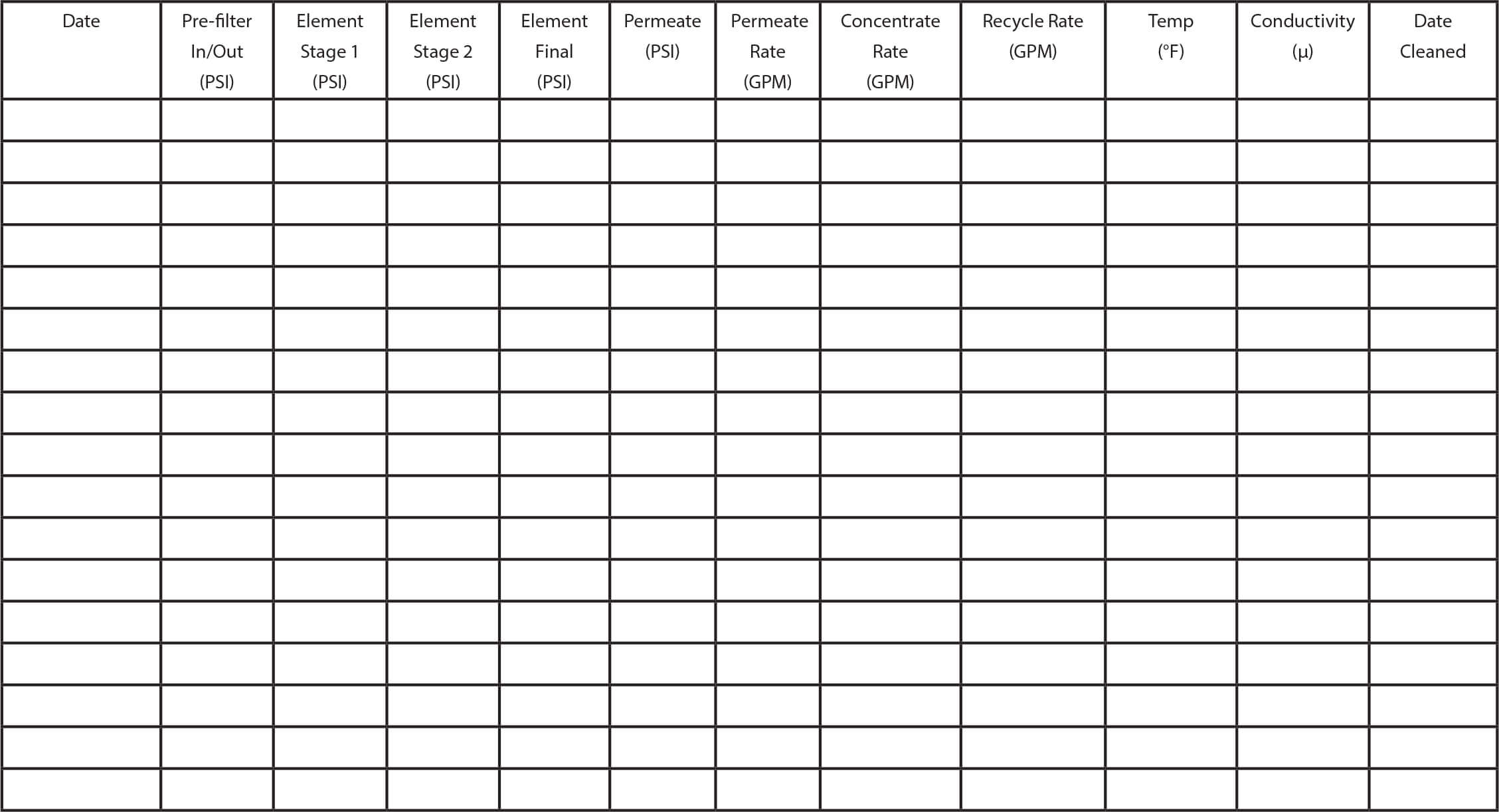
Daily Operation Log
Membrane Technology
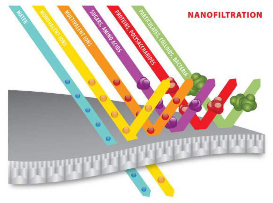
SELECTIVE TRANSPORT
Synder Filtration’s polymeric membranes are used to separate, concentrate, and/or fractionate a wide variety of liquids. Membranes serve as a thin barrier between miscible fluids that allow for preferential transport of one or more feed components when a driving force is applied, such as a pressure differential.
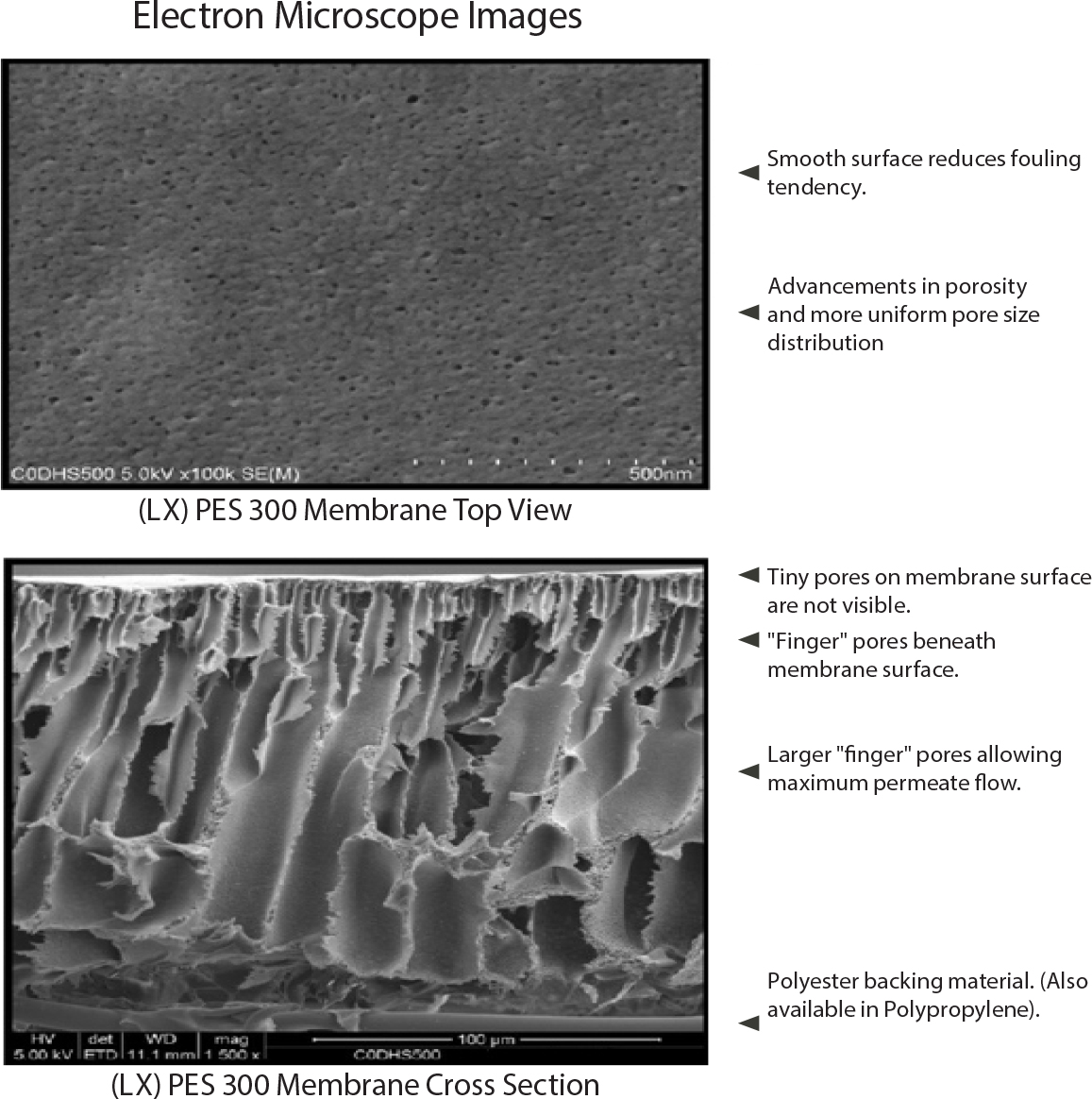
ASYMMETRIC PORE STRUCTURE
Synder membranes feature an asymmetric pore structure. Small surface pores control rejection of target molecules while large “finger pores” beneath the membrane surface allow permeate to move quickly through to a more open permeate carrier. This combination, along with membrane thickness, offers an optimal combination of selectivity and permeate flux.
TANGENTIAL FLOW PROCESS
Spiral wound membrane elements are fed tangentially. When sufficient pressure or concentration differentials exist on the surface of the membrane, molecules smaller than the surface pores will be driven through it. This solution that passes through the membrane is called the permeate, while the solution rejected by the membrane is called the concentrate (or retentate).
MOLECULAR WEIGHT CUT-OFF AND MEMBRANE SELECTION
Depending on polymer types and preparation methods, most of the polymeric membranes have a wide bell-shape pore size distribution. The concept of Molecular Weight Cut-Off (MWCO) is used as a common way to characterize the pore size distribution for porous membranes, typically for Ultrafiltration and Microfiltration membranes. MWCO is defined as that molecular weight which is 90% rejected by the membrane [1] and such value can only be used as a reference due to the facts that large pore size distribution is intrinsic to polymeric membrane and that different membrane manufacturers have their own standard of measurements. Furthermore, retention is governed not only by size and shape of the solutes, but also by the electrostatic interaction and steric hindrance as well as solute membrane affinity such as hydrogen bonding. It can also be influenced by solution chemistry and ionic strength. Therefore, membrane
filtration is a trial-and-error process and pilot studies are recommended to select the best membrane for a specific application.
At Synder, Dextran (a branched, neutral charged polysaccharide) of various molecular weights is used to rate the nominal MWCO of our membranes. The unit of molecular weight (or, more correctly, mass) is Dalton [2]. From the same supplier, the membrane with higher MWCO is always more porous than the ones with lower MWCO, but these numbers should be used with caution when comparing between membranes made by different vendors as each might utilize its own qualification method. Synder is proud to have the widest MWCO selection of membranes for process optimization.
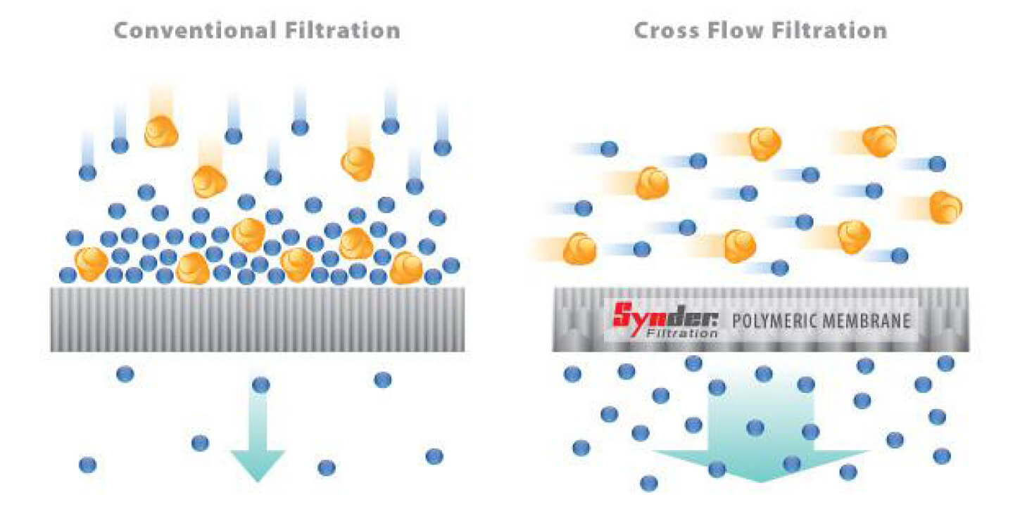
CONVENTIONAL VS. TANGENTIAL FLOW
Synder’s spiral wound membranes are designed for tangential flow (or cross flow) filtration, where the feed stream runs parallel to the membrane surface. Unlike conventional filtration where solids and solutes immediately accumulate on the membrane surface, tangential flow creates a sweeping (or shearing) force along the surface of the membrane to provide for longer filter life and less frequent cleaning cycles under normal operating conditions.
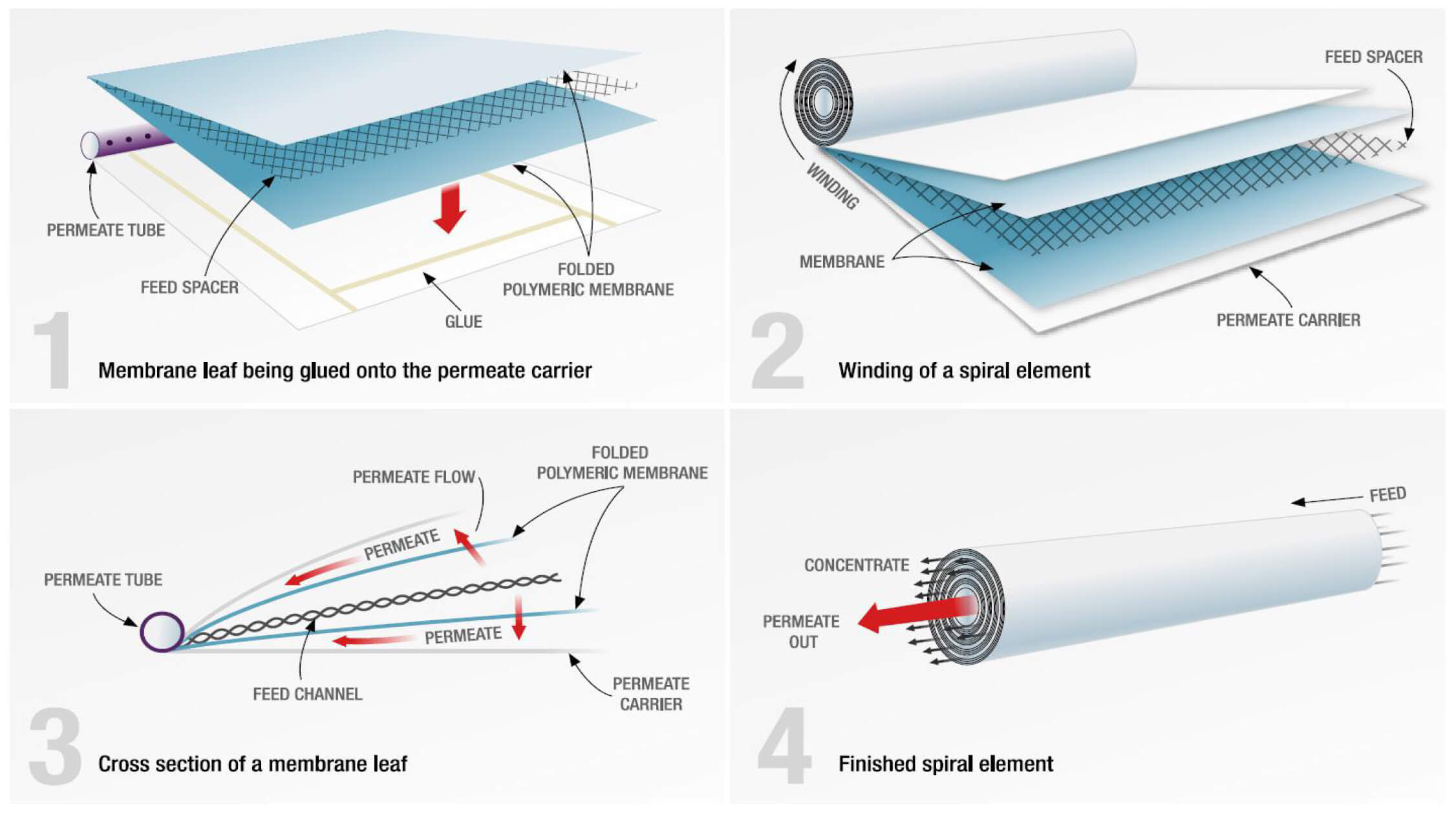
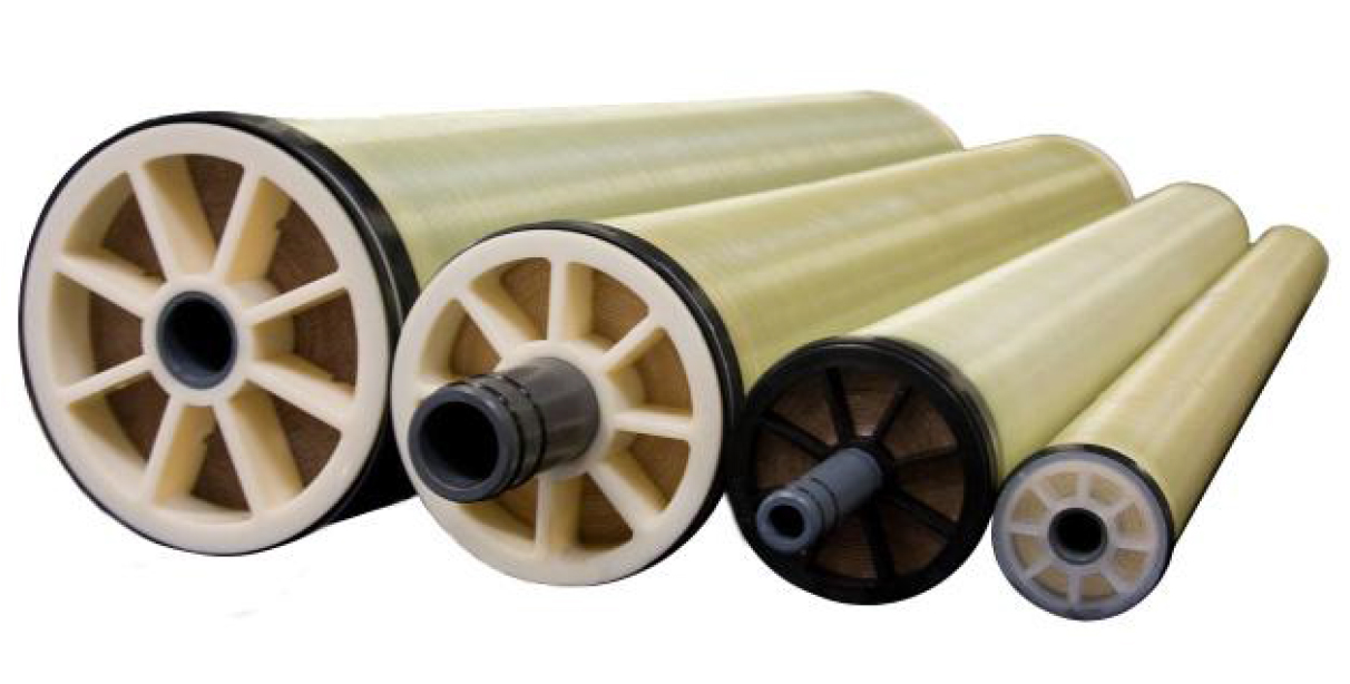
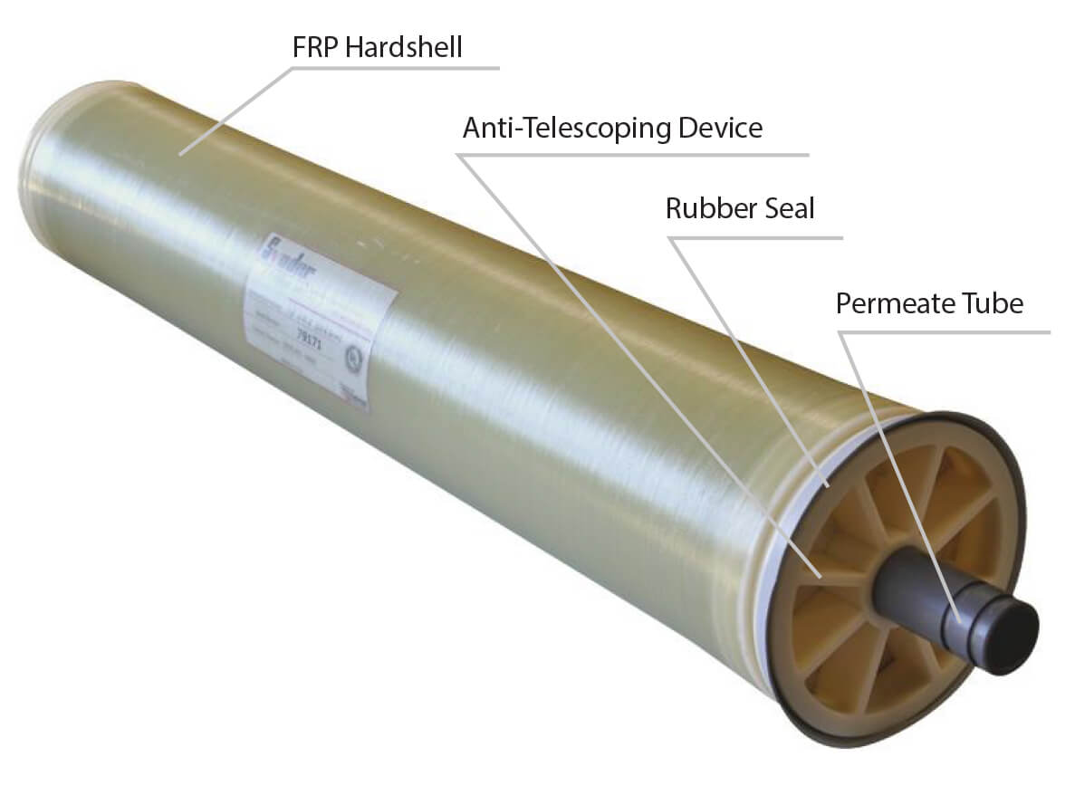
SPIRAL WOUND ELEMENT: A DISSECTION
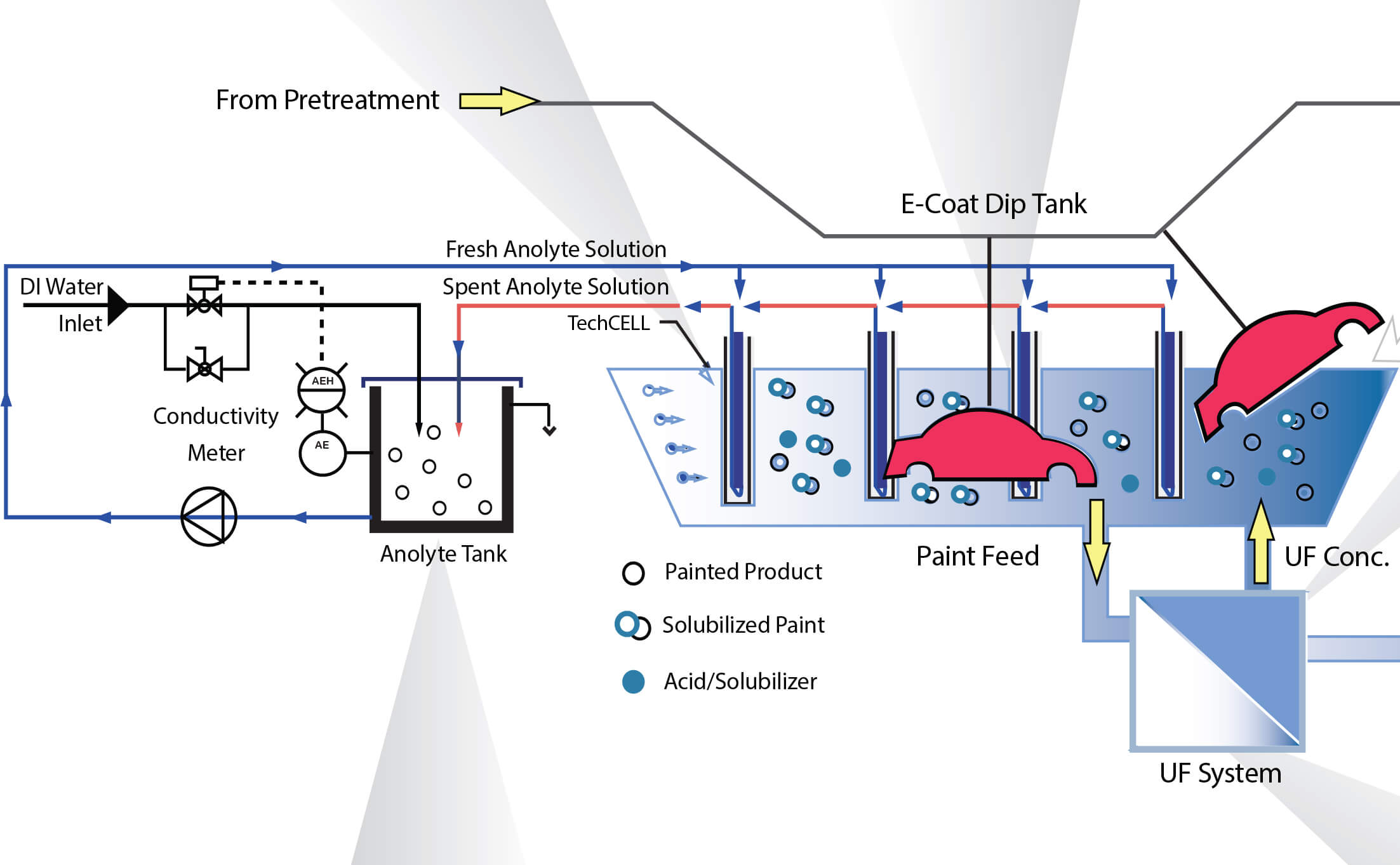
Electrocoat Process
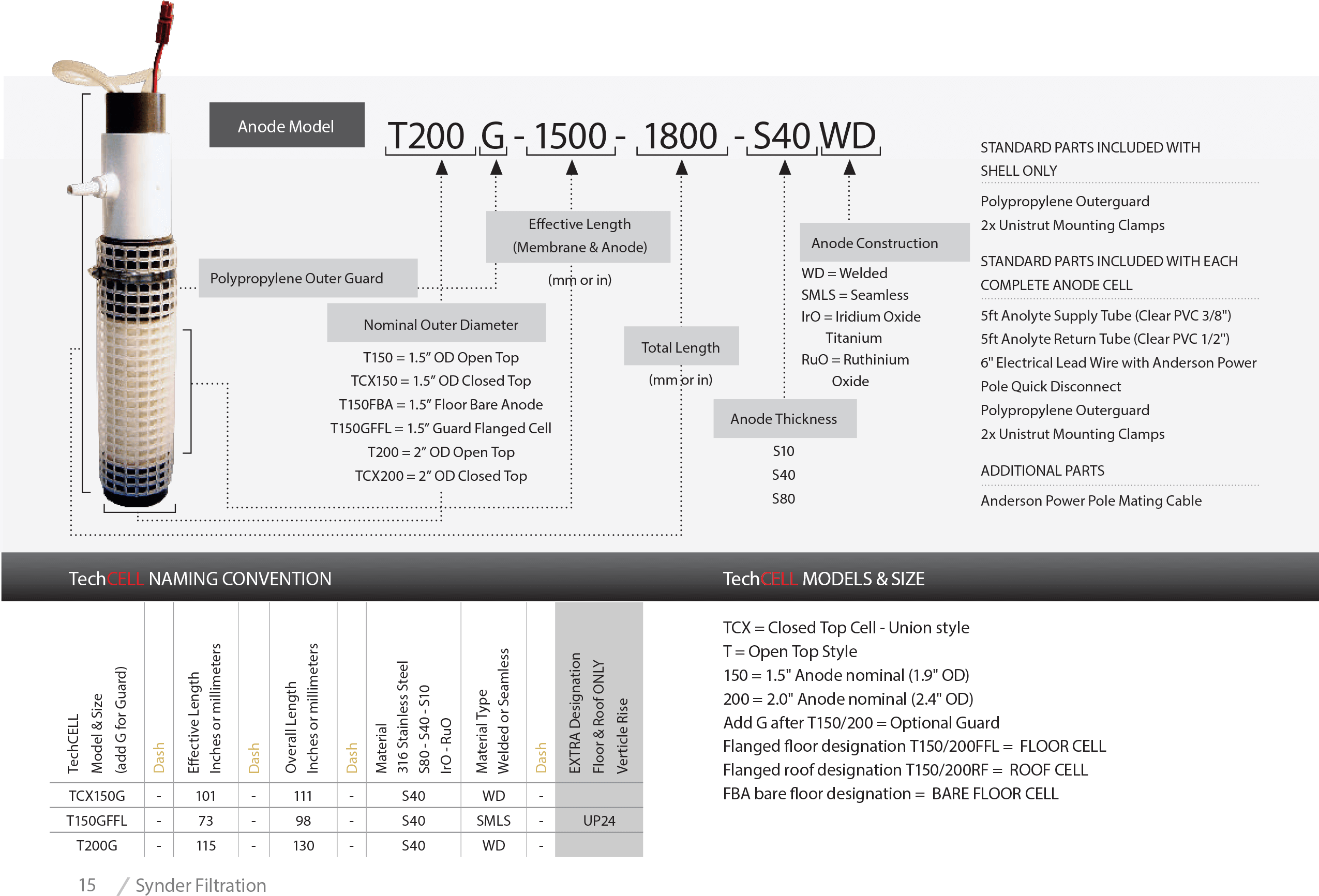
TechCELL
Synder’s TechCELL anode cell was specifically designed to optimize the electrocoating process. The tubular anode cell design is the preferred style for smaller industrial E-Coat lines.
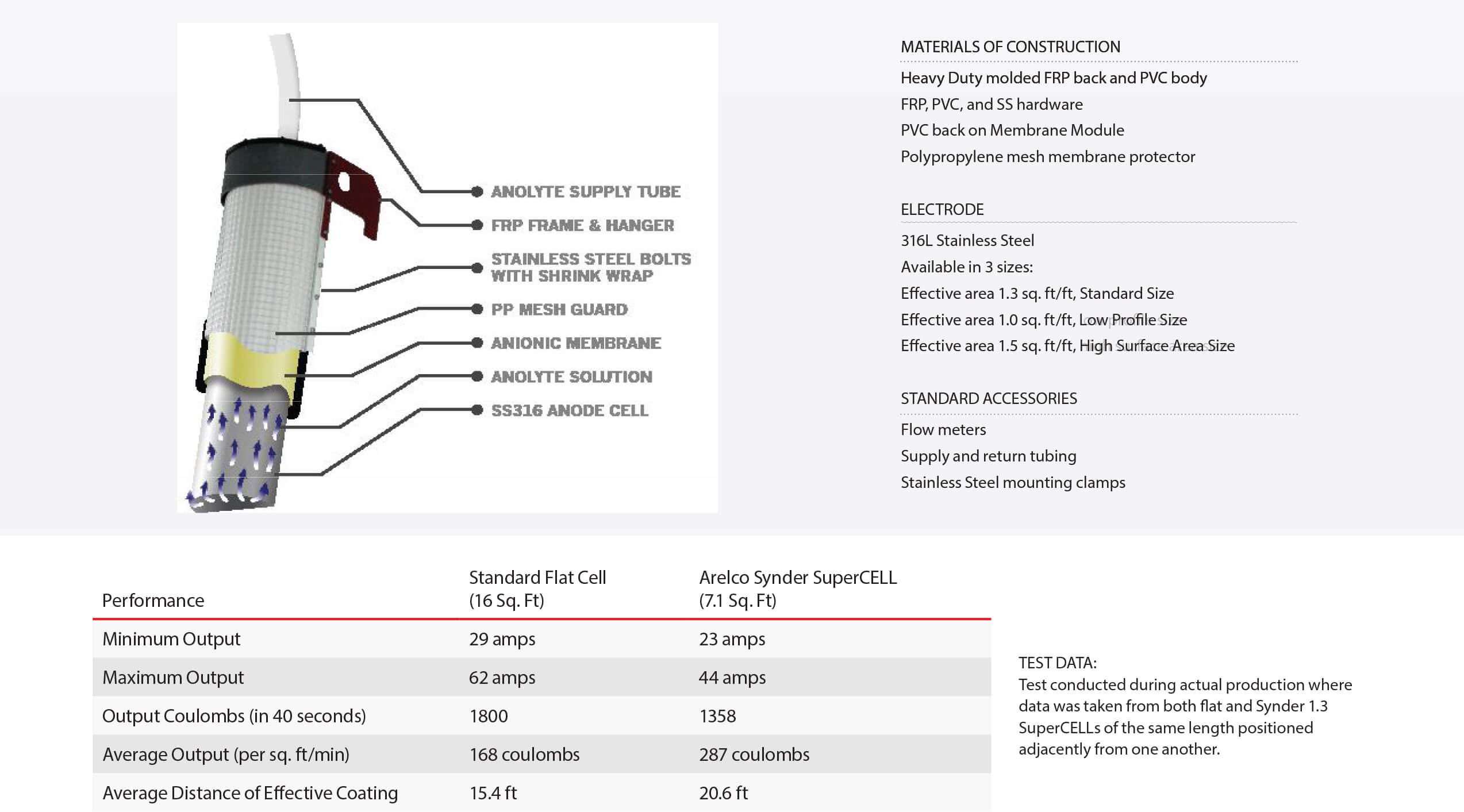
SuperCELL
The SuperCELL is a heavy duty, light weight, one piece C-Cell anode cell designed for optimum paint coverage in large electorocoat paint tanks. It offers incredible efficiency and performance with 100% of the cell facing the job.
Anolyte Recirculation System
Synder Filtration’s Anolyte Recirculation System offers advanced conductivity controllers, ultrasonic level sensors, and UV systems to meet the needs of both automotive and industrial E-Coat applications. Customization is readily available.
Ultrafiltration E-Coat Membrane Elements
Synder Filtration is a leading supplier of Ultrafiltration (UF) membranes and complete systems to the
E-Coat industry worldwide. With a full range of molecular weight cut-offs and element sizes for both
cathodic and anodic paint baths, Synder can outfit any E-Coat paint line with reliable ultrafiltration
membrane elements.
Ultrafiltration Systems
Synder Filtration offers a complete suite of membrane products for the E-Coat industry. Aside from our specially designed V Series elements which are well suited for any cathodic paint bath, we offer custom built Electrodeposition Ultrafiltration Systems (EDUF) which guarantee optimal performance for your paint process.
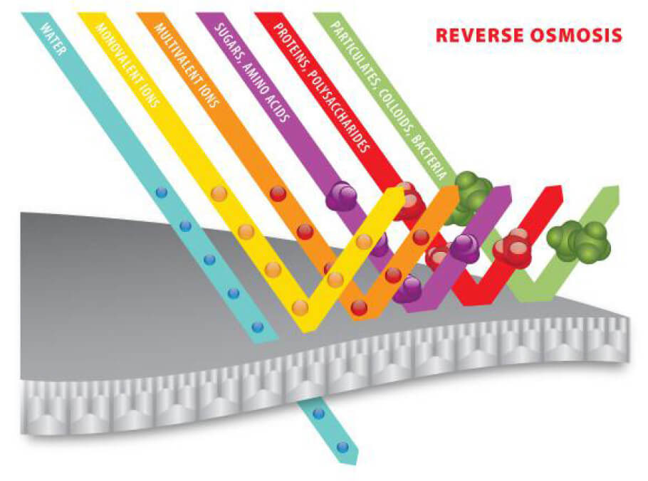
Reverse Osmosis Systems
Synder Filtration’s Reverse Osmosis systems provide consistent water quality for industrial processes, creating pure water by rejecting more than 99% of all dissolved solids in most cases.
Synder Membrane Range
Also available in Flat Sheets
Synder Filtration offers a complete line of Nanofiltration (NF), Ultrafiltration (UF), and Microfiltration (MF) membranes in a variety of
different flat sheet and membrane roll options. With sizes ranging from one square foot to thousands of linear feet, Synder can supply
membrane for all scales of testing, research, and production with exceptionally fast lead times.
| Membrane | Type | Polymer | Molecular Weight Cut-Off |
| NFS | NF | TFC | 100-250 |
| NFX | NF | TFC | 150-300 |
| NFW | NF | TFC | 300-500 |
| NFG | NF | TFC | 600-800 |
| XT | UF* | PES | 1,000 |
| VT | UF* | PES | 3,000 |
| MT | UF* | PES | 5,000 |
| ST | UF* | PES | 10,000 |
| SM | UF* | PES | 20,000 |
| MK | UF* | PES | 30,000 |
| MQ | UF* | PES | 50,000 |
| LY | UF* | PES | 100,000 |
| LV | UF* | PES | 200,000 |
| LX | UF* | PES | 300,000 |
| PZ | UF | PAN | 30,000 |
| PY | UF | PAN | 100,000 |
| PX | UF | PAN | 400,000 |
| V3 | UF*1 | PVDF | 30,000 |
| V4 | UF*1 | PVDF | 70,000 |
| V5 | UF*1 | PVDF | 200,000 |
| V6 | UF*1 | PVDF | 500,000 |
| V7 | UF*1 | PVDF | 800,000 |
| BN | UF* | PVDF | 50,000 |
| BY | UF* | PVDF | 100,000 |
| BX | UF* | PVDF | 250,000 |
| A6 | UF* | PVDF | 500,000 |
| FR | MF* | PVDF | 800,000 |
| V0.1 | MF* | PVDF | 0.1μm |
| V0.2 | MF* | PVDF | 0.2μm |
*MAX (High Temperature/High pH) Models Also Available
1Not Approved for Use in Food Contact Applications
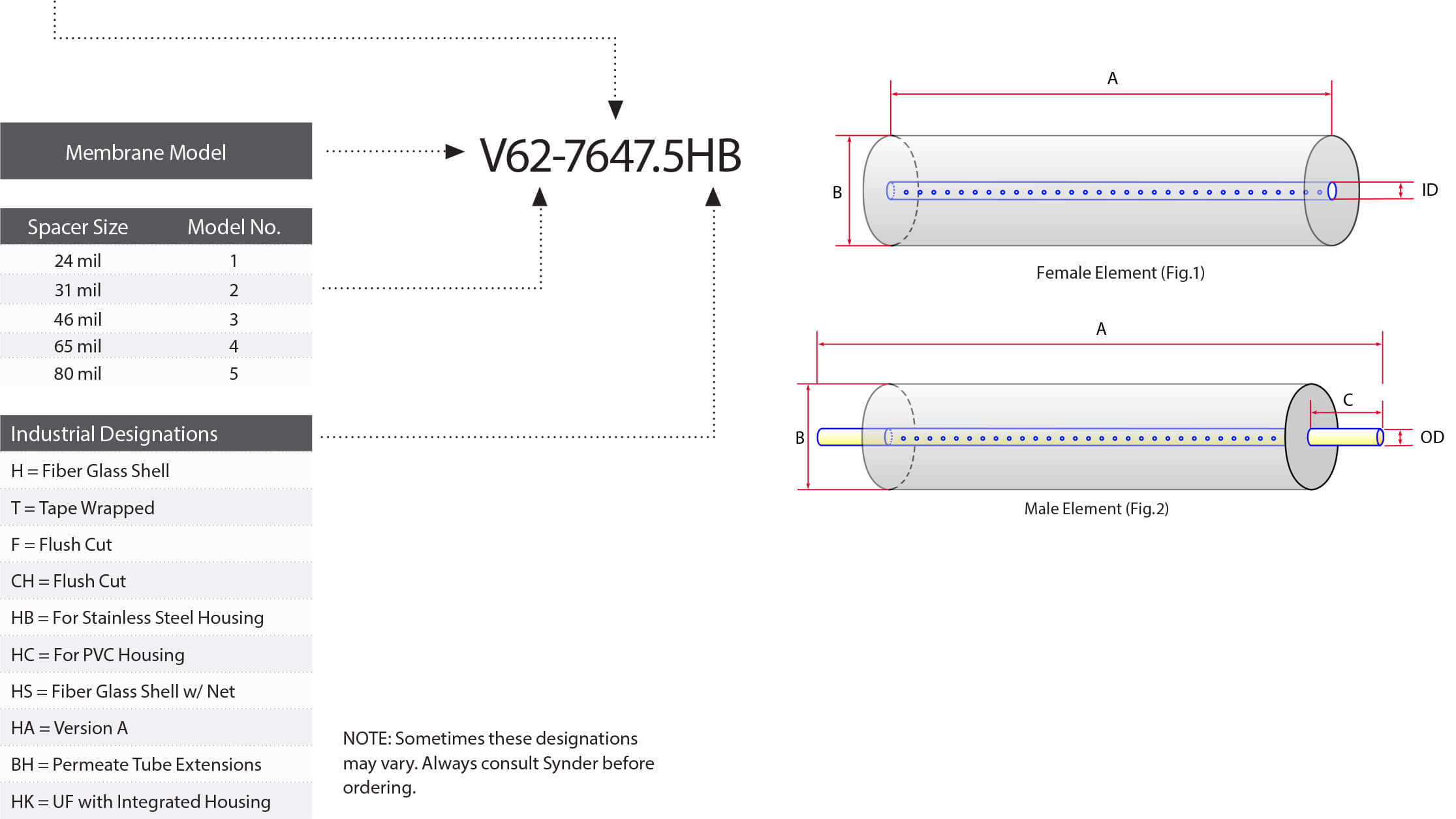
MODEL INFORMATION
| Size | Wet/Dry | Notes |
| 12” x 12” | Both Available | Custom Sizes / Shapes Available |
| 1m x 1m | Both Available | Custom Sizes / Shapes Available |
| Dry Roll | Dry Only | 800 Linear Foot Minimum |
Degrees of Separation
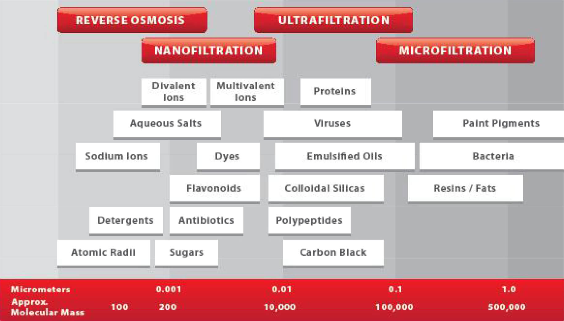
Note: 1 micrometer (micron) = 4 x 10⁻⁵ inches = 1 x 10⁴ Angstrom units
Solutions with Membrane Technology
With over 20 years of application knowledge and experience, Synder Filtration is committed to creating value with membrane technology. In addition to our most common applications listed below, Synder’s process engineers have a deep understanding of how to evaluate new applications efficiently and effectively. Stocking a fleet of pilot systems for all types and sizes of pilot studies, Synder Filtration is ready to help you develop your unique process.
INDUSTRIAL APPLICATIONS
Electrocoat Paint
Synder’s Ultrafiltration membranes have become a world standard across the electrocoat paint industry.
| Recommended Membranes | V3 (30kD), V4 (70kD), V5 (200kD), V6 (500kD), V7 (800kD), A6 (500kD) |
Landfill Leachate Treatment
Nanofiltration membranes in landfill leachate operations can be integrated as a post treatment to MBR processes to help meet discharge regulations.
| Recommended Membranes | NFW (300-500Da) |
Demineralization of Sea Water
Synder’s Nanofiltration membranes offer and excellent combination of divalent rejection and monovalent selectivity for seawater demineralization.
| Recommended Membranes | NFX (150-300Da), NFW (300-500Da) |
Organic Acid Concentration
Nanofiltration membranes can concentrate and/or desalt organic acids during fermentation processes.
| Recommended Membranes | NFX (150-300Da), NFW (300-500Da) |
Amino Acid Production
Amino Acids produced by a fermentation process contain high levels of suspended solids. MF membranes can be used to not only achieve a high product recovery, but also maintain the amino acid’s integrity.
| Recommended Membranes | FR (800kD), V0.1 (0.1μm) |
Fermentation Broth Clarification
Synder offers a variety of MF membranes for fermentation broth clarification, providing a cost-effective and high-throughput alternative to classical centrifugation and flocculation techniques.
| Recommended Membranes | FR (800kD), V0.1 (0.1μm) |
Synder’s NFS membrane displays superior sulfate rejection and flux performance ideal for use in seawater sulfate removal applications within the oil & gas industry.
| Recommended Membranes | NFS (100-250Da) |
Chlor-Alkali Process
Synder’s NFS membrane demonstrates excellent sulfate rejection and permeate flux, even in high salinity brine solutions, making it wellsuited
for use in chlor-alkali processes.
| Recommended Membranes | NFS (100-250Da) |
Flat Sheet for MBR Plate & Frame Systems
In waste water treatment, Microfiltration flat sheet membranes can be integrated with MBR to provide a true physical barrier for the elimination
of bacteria and other unwanted microbes.
| Recommended Membranes | FR (800kD), V0.1 (0.1μm) |
Oil Removal in Wastewater Treatment
Synder’s PX membrane is effective for the separation and removal of oils present in many industrial wastewater streams, in order to accomodate stringent discharge regulations and growing manufacturing costs.
| Recommended Membranes | PX (400kD) |
FR Membrane & Parallel-Stranded (Ribbed) Feed Spacers
Synder’s FR (PVDF 800kD) membrane is ideal for applications involving the separation of fats, bacteria and large particulates. For applications
with higher solids levels, we also offer ribbed spacers available in 46 and 80mil options.
| Recommended Membranes | FR (800kD) |
The Synder Difference
INDUSTRY LEADING SHIPPING TIMES
As a family-owned and financially independent company, we can afford to hold higher inventory levels and ship orders as quickly as possible. Synder Filtration constantly invests in large and diverse inventories of the most common membrane element models and sizes. This inventory matched with a global distribution network allows Synder to get you what you need, when you need it.
PERSONAL RESPONSE POLICY
Synder Filtration has a company-wide policy of personally responding to every customer inquiry within a day’s time. This policy is part of our overall commitment to provide our customers with an uncommon service experience. Whether your company employs 10 people or 10,000 people, we offer the same attention and deep product knowledge that you’ve come to expect from your most preferred vendors.
CUSTOM ELEMENTS & PRODUCT DEVELOPMENT
We have developed the widest range of polymeric Ultrafiltration membrane molecular weight cut-offs of any manufacturer in the world. Despite this tremendous accomplishment, our product line continues to evolve with the needs of our customers. With a highly flexible production line, we can quickly alter our manufacturing schedule to incorporate rush orders of the most uncommon models and sizes.
QUALITY POLICY
 Synder is proud to be ISO-9001:2015 Certified. At Synder, we believe quality is a way of life. We not only pride ourselves in providing a premium product, but in the relationships we forge with our customers in both seeking out new applications and optimizing established ones.
Nanofiltration Membrane Elements
Synder’s wide range of Nanofiltration membranes are engineered to provide optimal performance in both flux and rejection in a variety of process
applications.

MEMBRANE TYPES
| Membrane Model |
Polymer | Approx. Molecular Weight Cutoff |
Typical Operating Flux |
Average MgSO4 Rejection1 |
Average NaCl Rejection2 |
Average Lactose3 Rejection |
| NFS | Proprietary | 100-250Da | 30-40 GFD | 99.5% | 50.0% | 99.5% |
| NFX | Proprietary | 150-300Da | 20-25 GFD | 99.0% | 40.0% | 99.0% |
| NFW | Proprietary | 300-500Da | 45-50 GFD | 97.0% | 20.0% | 98.5% |
| NFG | Proprietary | 600-800Da | 55-60 GFD | 50.0% | 10.0% | 60.0% |
1Test Conditions 2,000ppm MgSO4 Solution at 110PSI (760 kPa) operating pressure, 77° F (25° C)
2Test Conditions 2,000ppm NaCl Solution at 110PSI (760 kPa) operating pressure, 77° F (25° C)
3Test Conditions 2% Lactose Solution at 110PSI (760 kPa) operating pressure, 77° F (25° C)
WHY SYNDER NF MEMBRANES?
- Optimized flux and rejection
- Operate at lower pressures than Reverse Osmosis membranes and still achieve excellent rejection of polyvalent ions
- Greatly reduce levels of hardness, nitrates, sulfates, tannins, turbidity, color, TDS, and moderate levels of salt from feed streams
CUSTOMIZATION WITH EXCEPTIONAL SPEED
Synder typically stocks the most common models for each membrane, however, elements can be customized and delivered with unparalleled lead times.
Call or Email Synder today with the following information to have an element made to your exact specifications:
- Element Outer Diameter/Housing Inner Diameter
- Permeate Tube Diameter
- Element Length
RECOMMENDED OPERATING PARAMETERS
| Maximum Operating Pressure | 600psi (4,137kPa) if T<95˚F (35˚C) 435psi (3,000kPa) if T>95˚F (35˚C) |
| Maximum Temperature | Continuous Operation: 122˚F (50˚C) Clean-In-Place (CIP): 104˚F (40˚C) |
| pH Range | Operating Parameters At Max Temp. – NFS/NFX: 3-9.5 NFW/NFG: 4-9 At Ambient Temp. – NFS/NFX: 3-10.5 NFW/NFG: 4-10Cleaning Parameters At Max Temp. – NFS/NFX: 2-11 NFW/NFG: 3-10 At Ambient Temp. – NFS/NFX: 2-11 NFW/NFG: 3-10.5 |
| Maximum Pressure Drop | Per Element: 15psi (103kPa) |
| Chlorine Tolerance | 500 ppm hours, Dechlorination Recommended |
NF Spiral-Wound Industrial Elements
DIMENSIONS & WEIGHT
| Element | Model Number | Diameter (B) in (cm) |
Length (A) in (cm) |
PWT ID/OD in (cm) |
Tube Extension (C) in (cm) |
Dry Weight lb (kg) |
| 1.8” | 1812TM | 1.8 (4.6) | 11.75 (29.8) | 0.675 (1.7) | 0.75 (1.90) | 1.0 (0.5) |
| 2.5” | 2519HF | 2.4 (6.1) | 19.0 (48.3) | 0.625 (1.6) | – | 3.0 (1.4) |
| 2540TM | 2.4 (6.1) | 40.0 (101.6) | 0.75″(1.9) | 1.0 (2.54) | 6.0 (2.7) | |
| 2540HF | 2.4 (6.1) | 40.0 (101.6) | 0.625 (1.6) | – | 6.0 (2.7) | |
| 2540HM | 2.4 (6.1) | 40.0 (101.6) | 0.75 (1.9) | 1.0 (2.54) | 6.0 (2.7) | |
| 4.0” | 4040TM | 3.9 (9.9) | 40.0 (101.6) | 0.75 (1.9) | – | 12.0 (5.5) |
| 4040HM | 3.9 (9.9) | 40.0 (101.6) | 0.75 (1.9) | 1.0 (2.54) | 12.0 (5.5) | |
| 4040HF | 3.9 (9.9) | 40.0 (101.6) | 0.625 (1.6) | – | 12.0 (5.5) | |
| 8.0″ | 8040HF | 7.9 (20.1) | 40.0 (101.6) | 1.125 (2.9) | – | 35.0 (15.9) |

RECOMMENDED ELEMENT CROSS FLOW RATE
Feed Spacer (in mils)
| Element | 24 | 31 | 46 | 65 | 80 | |
| 1.8” | m3/hr gpm |
0.4 1.8 |
0.5 2.0 |
0.6 2.4 |
0.6 2.5 |
0.6 2.6 |
| 2.5” | m3/hr gpm |
1.2 5 |
1.4 6 |
1.6 7 |
1.8 8 |
2.1 9 |
| 4.0” | m3/hr gpm |
2 10 |
4 18 |
5 21 |
5 23 |
6 24 |
| 8.0″ | m3/hr gpm |
10 43 |
11 48 |
13 55 |
14 61 |
15 64 |
The recommended cross flow rate will be subject to differential pressure limitations and specific applications.
MEMBRANE AREA (SQ. FT.)
Feed Spacer (in mils)
| Element | 24 | 31 | 46 | 65 | 80 |
| 1812TM | 4.0 | 3.4 | 2.6 | 2.0 | 1.6 |
| 2540HF | 35 | 30 | 23 | 17 | 15 |
| 2540HM | 33 | 28 | 21 | 16 | 14 |
| 4040HM | 99 | 87 | 68 | 51 | 43 |
| 4040HF | 96 | 82 | 64 | 50 | 42 |
| 8040HF | 440 | 380 | 293 | 227 | 193 |
CUSTOMIZATION WITH EXCEPTIONAL SPEED
Synder typically stocks the most common models for each membrane, however, elements can be customized and delivered with unparalleled lead times. For element
sizes not listed, please call or e-mail Synder today with the following information to have an element made to your exact specifications:
- Element Outer Diameter (OD) or Housing Inner Diameter (ID)
- Permeate Tube Diameter
- Element Length
- Specified MWCO, if applicable.
Note: Additional feed spacers are also available. Trials should be conducted to determine optimal application conditions.
Ultrafiltration & Microfiltration Elements
Synder Filtration’s Ultrafiltration and Microfiltration elements are available in a highly comprehensive range of MWCO’s. Contact us today to learn more about our complete line of membrane products and services.
MEMBRANE MODELS
| MODEL | MWCO | MATERIAL |
| XT | 1,000 | PES |
| VT | 3,000 | PES |
| MT | 5,000 | PES |
| ST | 10,000 | PES |
| SM | 20,000 | PES |
| MK | 30,000 | PES |
| MQ | 50,000 | PES |
| LY | 100,000 | PES |
| LV | 200,000 | PES |
| LX | 300,000 | PES |
| PZ | 30,000 | PAN |
| PY | 100,000 | PAN |
| PX | 400,000 | PAN |
| V3 | 30,000 | PVDF |
| V4 | 70,000 | PVDF |
| V5 | 200,000 | PVDF |
| V6 | 500,000 | PVDF |
| V7 | 800,000 | PVDF |
| BN | 50,000 | PVDF |
| BY | 100,000 | PVDF |
| BX | 250,000 | PVDF |
| A6 | 500,000 | PVDF |
| FR | 800,000 | PVDF |
| V0.1 | 0.1 μm | PVDF |
| V0.2 | 0.2 μm | PVDF |
INDUSTRIAL ELEMENT OPERATING SPECIFICATIONS
| Membrane Type | Membrane Construction |
| Proprietary PES, PVDF or PAN | Spiral-Wound with netted outerwrap or fiber glass hardshell (FRP) |
| Pressure | PSI | Bar |
| Max. Inlet Pressure | 116 | 8.0 |
| Min. Outlet Pressure | 10 | 0.7 |
| Max. Differential Pressure per Element | 18 | 1.2 |
| Max. Permeate Backpressure | 5 | 0.3 |
NOTE: Soft start on boost pumps required to minimize pressure/flow shocks to elements.
| Temperature | Fahrenheit | Celsius |
| Max. Operating | 122° | 50° |
| Max. CIP Temperature | 122° | 50° |
| PH Parameters | pH |
| pH Range during Operation at 25°C Max. | PES/PVDF: 1.0 – 11.0 | PAN: 3.0-10.0 |
| pH Range during CIP at 50°C Max. | PES/PVDF: 2.0 – 11.0 | PAN: 3.0-10.5 |
| Peroxide | Max. ppm |
| Free Peroxide in Product during Operation | < 3 ppm |
| Peroxide as a Sanitizer at 25°C Max, pH 6-7 10 minutes recirculation |
0.1% |
| Chlorine | Norm. ppm | Max. ppm |
| Free Chlorine in DF Water or Product |
0 | < 0.1 |
| Chlorine during CIP at: pH 10.8-11.0 and 50°C (PES/PVDF) pH 10.5 and 50°C (PAN) |
150 | 180 |
NOTE: Maximum chlorine exposure for all elements is 30 minutes per day at pH and temperature conditions listed above.
UF/MF Spiral-Wound Industrial Elements
DIMENSIONS & WEIGHT
| Element | Model Number | Diameter (B) in (cm) |
Length (A) in (cm) |
PWT ID/OD in (cm) |
Tube Extension (C) in (cm) |
Dry Weight lb (kg) |
| 1.8” | 1812TM | 1.8 (4.6) | 11.75 (29.8) | 0.675 (1.7) | 0.75 (perm) 1.00 (plug) | 1.0 (0.5) |
| 2.5” | 2540TM | 2.4 (6.1) | 40.0 (101.6) | 0.75 (1.9) | 1.0 (2.54) | 4.0 (1.8) |
| 2540HF | 2.4 (6.1) | 40.0 (101.6) | 0.625 (1.6) | – | 4.0 (1.8) | |
| 2540HM | 2.4 (6.1) | 40.0 (101.6) | 0.75 (1.9) | 1.0 (2.54) | 4.0 (1.8) | |
| 4.0” | 4040TM | 3.9 (9.9) | 40.0 (101.6) | 0.75 (1.9) | 1.0 (2.54) | 12.0 (5.5) |
| 4040HM | 3.9 (9.9) | 40.0 (101.6) | 0.75 (1.9) | 1.0 (2.54) | 12.0 (5.5) | |
| 4040HF | 3.9 (9.9) | 40.0 (101.6) | 0.625 (1.6) | – | 12.0 (5.5) | |
| 8.0″ | 7940HF | 7.9 (20.1) | 40.0 (101.6) | 1.138 (2.9) | – | 35.0 (15.9) |
| 8040HF | 7.9 (20.1) | 40.0 (101.6) | 1.125 (2.9) | – | 35.0 (15.9) |

RECOMMENDED ELEMENT CROSS FLOW RATE
Feed Spacer (in mils)
| Element | 24 | 31 | 46 | 65 | 80 | |
| 1.8” | m3/hr gpm |
0.7 3 |
0.8 3 |
0.9 4 |
1.0 4 |
1.1 5 |
| 2.5” | m3/hr gpm |
1.3 6 |
1.5 7 |
1.8 8 |
2.0 9 |
2.1 9 |
| 4.0” | m3/hr gpm |
3 15 |
4 17 |
5 20 |
5 23 |
6 24 |
| 8.0″ | m3/hr gpm |
15 66 |
17 75 |
20 89 |
23 99 |
24 105 |
The recommended cross flow rate will be subject to differential pressure limitations and specific applications.
MEMBRANE AREA (SQ. FT.)
Feed Spacer (in mils)
| Element | 24 | 31 | 46 | 65 | 80 |
| 1812TM | 3.1 | 2.7 | 2.7 | 1.6 | 1.3 |
| 2540HF | 28 | 24 | 20 | 16 | 13 |
| 2540HM | 30 | 26 | 22 | 17 | 14 |
| 4040HM | 81 | 72 | 58 | 46 | 39 |
| 4040HF | 86 | 75 | 61 | 49 | 41 |
| 7940HF | 379 | 335 | 268 | 210 | 178 |
| 8040HF | 379 | 335 | 268 | 210 | 178 |
STANDARD SERIES BENEFITS
- Wide range of UF MWCO’s available
- Good pH and temperature resistance
- High resistance to fouling
- Customizable dimensions for unique housings
- V Series has a proprietary hydrophilic charge
for improved performance - Easy to clean with membrane cleaning chemicals
- Integrated end plugs reduce possible points of leakage
TECHNICAL NOTES
For element sizes not listed, please call or e-mail Synder Filtration for details. We can design an element to fit your exact needs – just specify the element outer diameter (OD) or vessel/housing inner diameter (ID), permeate tube inner diameter (ID), or outer diameter (OD), and length. Additional feed spacers are also available.
Ultrafiltration E-Coat Membranes
THE INDUSTRY STANDARD
Synder Filtration is a leading supplier of Ultrafiltration (UF) membranes and complete systems to the E-Coat industry worldwide. With a full range of molecular weight cut-offs and element sizes for both cathodic and anodic paint baths, Synder can outfit any E-Coat paint line with reliable
ultrafiltration membrane elements.
FEATURES & BENEFITS
- The V series has a proprietary hydrophilic charge to repel paint particles and promote maximum flux rates.
- Additional charging not required.
- Membrane only requires one cleaning chemical plus acid. No other additives required.
- Integrated end plugs allow for easy integration and removal.
- Synder maintains the largest E-Coat devoted sales, engineering, and support staff of any membrane manufacturer in the world.
COMPREHENSIVE TECHNICAL SUPPORT
- Paint/MEQ analysis
- UF system optimization
- Anolyte system optimization
- Personalized technical support
MEMBRANE TYPES
| MODEL | MWCO | MATERIAL |
| V3 | 30,000 | PVDF* |
| V4 | 70,000 | PVDF* |
| V5 | 200,000 | PVDF* |
| V6 | 500,000 | PVDF* |
| V7 | 800,000 | PVDF* |
| A6 | 500,000 | PVDF* |
*The “V” series was specifically designed for processing cathodic paint, while the A6 is intended for processing anodic paint. V6 (PVDF 500kDa) is the most popular product for processing cathodic paint.
RECOMMENDED OPERATING PARAMTERS
| Typical Operating Flux | 5-35 GFD (8-60 LMH) |
| Membrane Type | Synder Proprietary |
| Membrane Construction | Spiral-Wound with netted or fiber glass outer wrap |
| Maximum Temperature | Continuous Operation: 122˚F (50˚C) Clean-In-Place (CIP): 110˚F (43.3˚C) |
| pH Range | Continuous Operation: 1-11 Clean-In-Place (CIP): 2-10.5 |
| Maximum Pressure Drop | FRP Element: 35psi (241kPa) Net Wrap Element: 17psi (117kPa) |
| Chlorine Tolerance | 180ppm maximum per cleaning cycle |
UF E-Coat Spiral-Wound Industrial Elements
DIMENSIONS & WEIGHT
| Model # | (A) Length in (mm) |
(B) Element OD in (mm) |
Perm Tube ID (Female) in (mm) |
Perm Tube OD (Male) in (mm) |
(C) Tube Ext Length (Male) |
Feed Rate GPM (LPM) |
Standard Housing |
| 1812TM | 10.00 (254.0) | 1.8 (45.7) | 0.675 (17.1) | 0.75 (perm) 1.0 (plug) | 2.0 (7.6) | IH-1812M | |
| 2519H | 19.25 (489.0) | 2.5 (63.5) | 0.62 (15.8) | 6.0 (23) | IH-2519 | ||
| 2540H | 38.00 (965.2) | 2.5 (63.5) | 0.75 (19.1) | 1.00 (both ends) | 6.0 (23) | IH-2540 | |
| 3940AH | 38.80 (985.5) | 3.93 (99.8) | 0.827 (21) | 0.60 (both ends) | 25 (95) | ||
| 3945H | 45.00 (1143) | 3.93 (99.8) | 0.62 (15.8) | 25 (95) | |||
| 4030H | 27.00 (658.8) | 3.93 (99.8) | 0.84 (21.3) | 3.00 (perm) 3.63 (plug) | 25 (95) | IH-4030 | |
| 4032H | 29.50 (749.3) | 3.93 (99.8) | 0.75 (19.1) | 1.06 (both ends) | 25 (95) | ||
| 4033H | 33.00 (838.2) | 3.93 (99.8) | 0.62 (15.8) | 25 (95) | |||
| 4037H | 27.00 (685.8) | 3.93 (99.8) | 0.84 (21.3) | 3.00 (perm) 8.625 (plug) | 25 (95) | IH-KR4 | |
| 4040AH | 40.00 (1016) | 3.93 (99.8) | 0.62 (15.8) | 25 (95) | |||
| 4040BH | 40.00 (1016) | 3.93 (99.8) | 0.76 (19.3) | 25 (95) | |||
| 4045BH | 40.00 (1016) | 3.93 (99.8) | 0.84 (21.3) | 3.00 (perm) 1.875 (plug) | 25 (95) | IH-4042 | |
| 4045CH | 45.00 (1143) | 3.93 (99.8) | 0.62 (15.8) | 25 (95) | |||
| 4051.5H | 40.00 (1016) | 3.93 (99.8) | 0.84 (21.3) | 3.00 (perm) 8.50 (plug) | 25 (95) | IH-40RF | |
| 5640H | 40.00 (1016) | 5.60 (142.2) | 1.29 (32.8) | 40 (151 | |||
| 5647.5H | 40.00 (1016) | 5.60 (142.2) | 1.66 (42.2) | 3.00 (perm) 4.375 (plug) | 40 (151 | IH-60A | |
| 5651.5H | 40.00 (1016) | 5.60 (142.2) | 1.66 (42.2) | 3.00 (perm) 8.375 (plug) | 40 (151 | IH-60RF | |
| 7637H | 33.00 (838.2) | 7.45 (189.2) | 1.66 (42.2) | 2.00 (both ends) | 70 (265) | ||
| 7640HB | 40.00 (1016) | 7.45 (189.2) | 1.29 (32.7) | 70 (265) | |||
| 7640HC | 40.00 (1016) | 7.28 (184.9) | 1.29 (32.7) | 70 (265) | |||
| 7647.5HB | 40.00 (1016) | 7.45 (189.2) | 1.66 (42.2) | 3.00 (perm) 4.375 (plug) | 70 (265) | IH-80S (SB) | |
| 7647.5HC | 40.00 (1016) | 7.28 (184.9) | 1.66 (42.2) | 3.00 (perm) 4.375 (plug) | 70 (265) | IH-80D (C,E) | |
| 7940HA | 38.25 (717.6) | 7.90 (200.7) | 1.66 (42.2) | 0.875 (both ends) | 80 (303) | ||
| F7940HA | 40.00 (1016) | 7.90 (200.7) | 1.139 (28.9) | 80 (303) | |||
| 8040H | 40.00 (1016) | 7.90 (200.7) | 1.125 (28.6) | 80 (303) |
TECHNICAL NOTES
For element sizes not listed, please call or e-mail Synder Filtration for details. We can design an element to fit your exact needs – just specify the element outer diameter (OD) or vessel/housing inner diameter (ID), permeate tube inner diameter (ID), or outer diameter (OD), and length. Additional feed spacers are also available.
TechCELLTM
Synder’s TechCELLTM anode cell was specifically designed to optimize the electrocoating process. This tubular anode cell design is the preferred
style for industrial E-Coat lines, due to a wider range of throw angles and part coverage.
HOW IT WORKS
Anolyte cells serve as an opposing electrode for the part being painted and also remove excess acid generated during electrodeposition.
Equipped with a robust anionic membrane, the electrical charge on these cells attract the excess acid in the paint bath and effectively remove them out of solution through membrane filtration.

TUBULAR CELL FEATURES AND BENEFITS
- More throw angles create better part coverage
- Larger membrane area, longer life leading to lower
capital & operating costs - Easy to use & maintain
- Flexibility for your tank
- Custom designs for different tanks and configurations
- Roof cells & floor cells available
BETTER THROW ANGLES
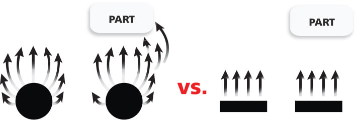 Tubular (Round) Anodes offer a greater range of electrical “throw angles” vs. flat cells. A greater variety of throw angles can significantly improve the coating quality and coverage in hard to reach areas of the part, or more complex geometries.
More throw angles also allow the anode to start painting sooner in monorail systems.
SuperCELLTM
The SuperCELLTM is a heavy duty, light weight, one piece C-Cell anode cell designed for optimum paint coverage in large electrocoat paint tanks. SuperCELL offers incredible efficiency and performance with 100% of the cell facing the job and is thus the most economic option for large volume paint tanks.
FEATURES AND BENEFITS
Lower Operating Costs-
- Increased amps per square foot and subsequent 50% savings in electrical power usage provide for dramatic reductions in operating costs
Better Coverage-
- More throw angles mean greater coverage and longer paint times in monorail systems.
Easy To Use & Maintain-
- Heavy duty, light weight, and in one piece to ensure easy lifting and simple power cable connections.
Flexibility For Your Tank-
- Available in four different sizes, including a low profile option for tanks with limited clearance between the part and tank wall.
SUPER CELL DESIGN
- A one piece anode cell
- Designed for ease in lifting and connecting to the power cable
- Weighs less than 1/3 of a standard flat cell
- No welds below the anolyte fluid to prevent failure due to submerged mechanical or welded connections
- Made from 10 gauge or 3/16” thick 316L stainless
BETTER THROW ANGLES
The SuperCELL offers a greater range of electrical “throw angles” vs. flat cells. A greater variety of throw angles can significantly improve the coating quality and coverage in hard to reach areas of the part.
More throw angles also allow the anode to start painting sooner in monorail systems.
Ultrafiltration & Microfiltration Systems
Synder Filtration offers a complete suite of membrane products for your industrial processes. Aside from our high performance Nanofiltration, Ultrafiltration and Microfiltration spiral elements, we offer custom built industrial filtration systems which provide optimal performance for your application. This premium quality product is achieved through a collaborative effort between our engineers and customers. During the design phase of industrial & sanitary systems, Synder’s engineers and R&D staff will work with the customers to perform pilot tests and ensure optimal design, sizing, and configuration. Together, we can build a fully customized system that is truly appropriate for your application, no matter how unique it may be.
STANDARD MODULE SYSTEM AND PARTS
- Housing Vessel
- Housing Flow Meters
- Stainless Steel Ball valves
- Butterfly Valves
- PVC Ball Valves
- Gauges/Isolator
STANDARD CIP SYSTEM PARTS
- CIP Pump
- One/Two Point
Temperature Switch - Cooling Coil
- CIP Tank Heater
- CIP Flow Meter
INDUSTRIAL SYSTEM FEATURES AND BENEFITS
- Various pretreatment options available
- CIP system: Clean a single element while rest of system remains online, or clean entire system all at once
- Our system includes add-on features such as data logging and remote monitoring capabilities
- Available bag filter in CIP loop
- Stainless Steel housings
- Stainless Steel top & bottom caps are standard
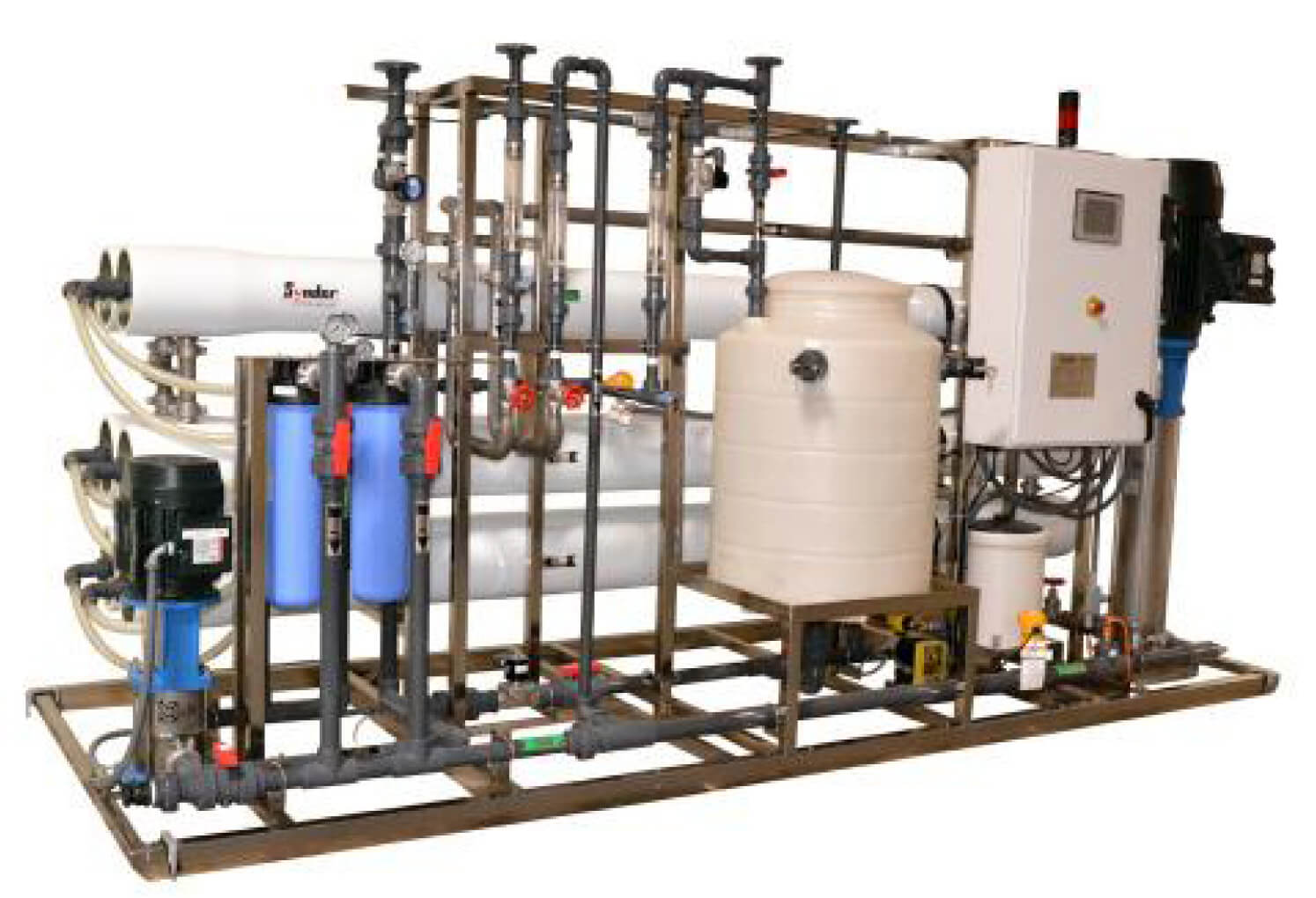
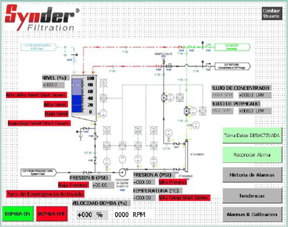
Nanofiltration & Reverse Osmosis Systems
Synder Filtration’s high pressure Nanofiltration and Reverse Osmosis systems are engineered for industrial process applications. Our expertise in custom-made equipment allows us to offer a wide range of different materials, instruments, and controls.
STANDARD FEATURES
- Onboard CIP system
- Touch screen operator interface auto purge on shutdown
- Stainless steel or epoxy coated carbon steel frame
- Stainless steel pumps
- Low energy membranes
- Pretreatment interlock
- 5 micron pre-filters
- Liquid filled gauges
- PLC controller
- Storage tank level
- Inlet Valve
- Inlet Pressure
- Pump Pressure
- Water Quality
- Feed Pump
- Touch-Screen HMI
- Conductivity & pH (if equipped)
- CIP Pump
- Booster Pump (if equipped)
OPTIONS
- Storage tank with transfer pump
- UV sterilizer for above
- Booster pump
- Chemical dosing
- Matched pretreatment equipment
- Cold water pump option
- Data logging
- Remote monitoring
- Fully-automated CIP
- Automated flow control
ADDITIONAL BENEFITS
- Reverse Osmosis and Nanofiltration membranes are a physical
barrier to microbes - Lower operating costs than other industrial water
purification methods - Portable cleaning/sanitizing systems
- Low environmental impact and
minimal chemical dosage required - Storage tank holds excess water, acting as a
buffer tank
NOTE: Optimum design is based on representative feed-water analyses, and Synder Filtration offers no performance guarantees, either expressed or implied, without complete knowledge of the chemical constituents in the feed stream.
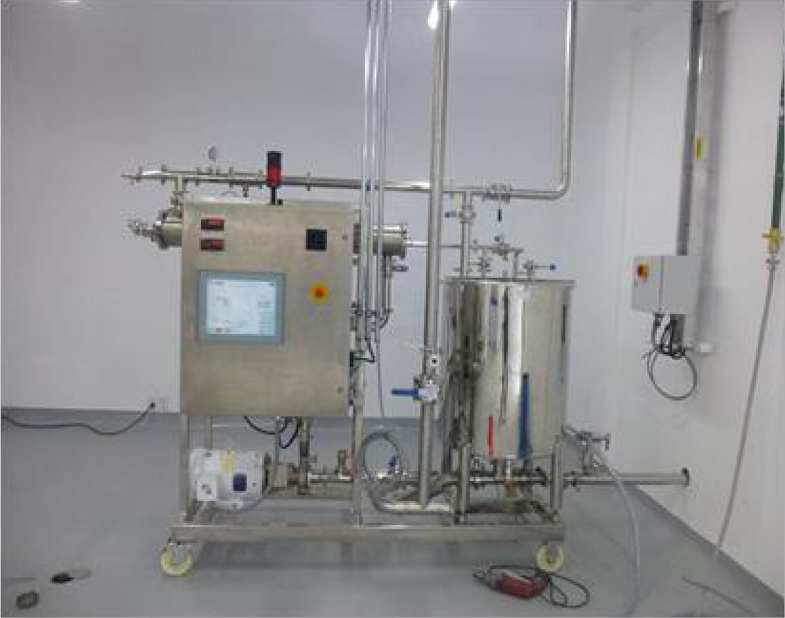
Sanitary Systems
Synder provides custom sanitary systems, and industrial systems with sanitary weld & component requirements. Many of the components are easily removeable and disassembled for cleaning, and have low interior surface roughness. From pilot units to production scale units, Synder’s Engineering team will work closely with the customer from design to manufacturing to ensure the system meets all specifications.
STANDARD SANITARY FEATURES
- Housing vessel
- Stainless steel valves
- Pressure gauges
- Pump
- Temperature sensor
- Flow sensor
- Custom tank with level sensor
SANITARY SYSTEM BENEFITS
Sanitary compenents are easily removal and can be disassembled for cleaning. Fine surface roughness and sanitary designs also prevent build-up and potential contamination.
OPTIONS AND CUSTOMIZATION
- Feed and booster pumps
- Feed and product storage tanks
- Custom system design and configuration
- Automation and controls customization
- Various PLC and controllers
- Custom PLC program and alarm features
- Custom touch screen HMI interfaces
- Data logging
- Remote monitoring
- Wide selection of sensors and instrumentations to best suit the customers needs
- Synder’s Engineering team will work with the customer to allow our systems to be integrated into their facility seamlessly
Anode Cell Current Monitoring System
The Anode Cell CMS (Current Monitoring System) is designed to measure an individual anode cell’s amp draw and monitor the overall performance and efficiency of the anode cell over time.
CMS FEATURES AND BENEFITS
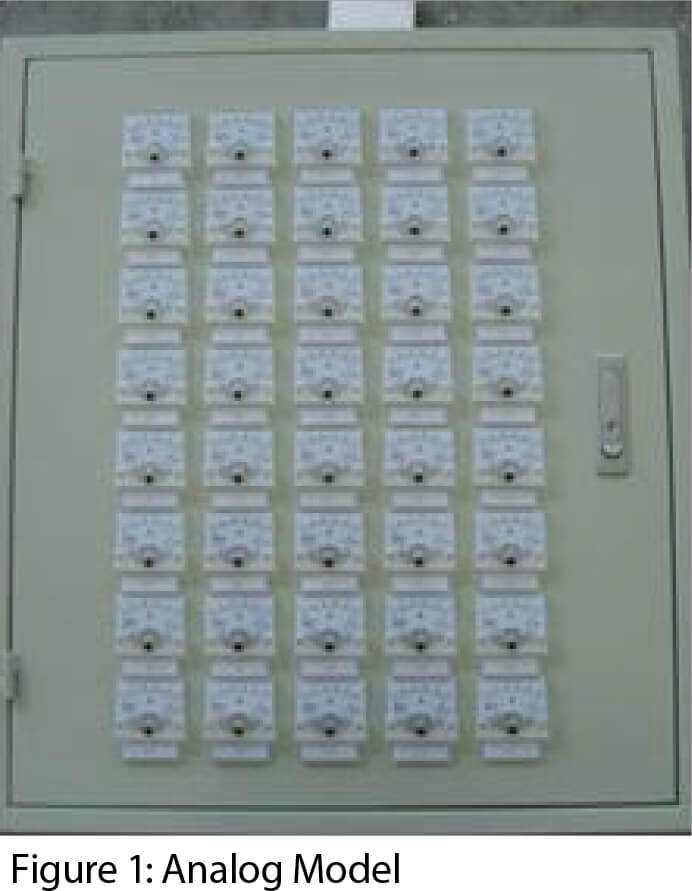
The CMS allows users to monitor the amp draw of individual TechCELLs, an indicator of TechCELL performance and condition. Monitoring TechCELL performance will assist in determining ideal configuration, and prevent product defects occurring in the paint bath. The analog model displays all amperage readings on individual analog meters on the panel while the PLC based model displays all readings on an HMI.
ANALOG CMS
The analog model (Figure 1) allows the user to monitor individual TechCELL amp draw simultaneously through analog meters mounted on the enclosure.
EASY INSTALLATION
No modification required for existing systems. The shunt sensors can be installed directly between the TechCELL and rectifier using existing quick connects.
HOW IT WORKS
Power from the rectifier passes through the shunt prior to entering the TechCELL and the resulting voltage drop across the shunt can then be measured and used to calculate amperage.
The signal from the shunt is then processed, and converted to amperage readings on the analog gauges or recorded into the PLC and displayed on the HMI.
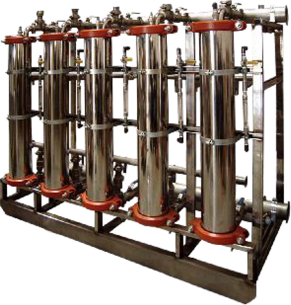
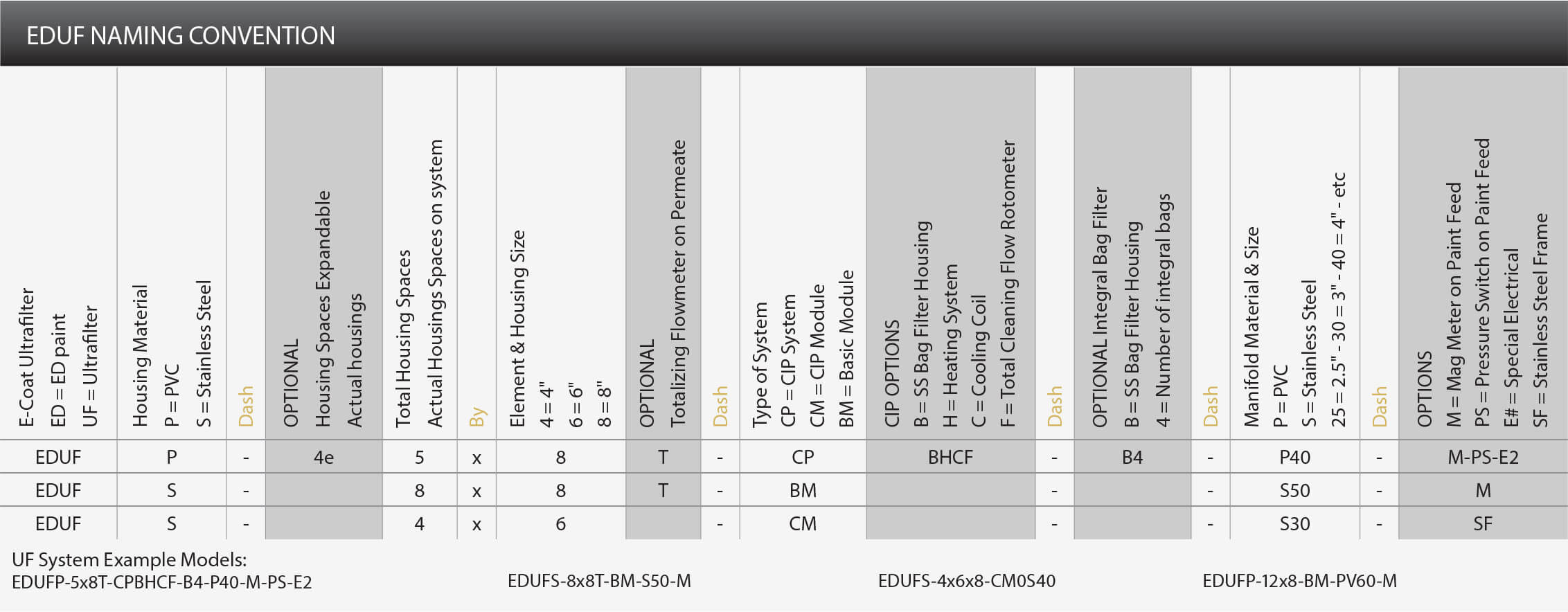
EDUF Systems
Synder Filtration offers a complete suite of membrane products for the E-Coat industry. Aside from our specially designed V Series elements which are well suited for any cathodic paint bath, we offer custom built Electrodeposition Ultra Filtration systems (EDUF) which guarantee optimal performance for your paint process. This premium quality product is achieved through a collaborative effort between our engineers and customers. Synder is proud to have a majority of
automotive system installations in North America.
UF SYSTEM OPERATING SPECIFICATIONS
| Operational Parameters and Limitations for Electro Deposition Systems | |
| Maximum operating pressure at element inlet | 60 PSIG |
| Maximum operating pressure at element outlet | 40 PSIG |
| Minimum operating pressure at element outlet | 5 PSIG |
| Minimum pressure drop per element at 70 GPM/element | 20 PSIG |
| Design pressure drop per element at 70 GPM/element | 25 PSIG |
| Maximum pressure drop per element at 70 GPM/element | 35 PSIG |
| Minimum feed rate per V62-7647.5H element | 65 GPM |
| Design feed rate per V62-7647.5H element | 70 GPM |
| Maximum operating temperature/cleaning | |
| (Schedule 80 PVC piped EDUF System) | 120° F @ 50 PSI |
| (Stainless Steel / CPVC piped EDUF System) | 140° F @ 110 PSI |
| Maximum operating temperature/paint – per paint manufacturer’s specifications | |
| Maximum pressure at permeate outlet | 5 PSIG |
| Recommended cleaning pressure profiles | 25 – 30 PSI inlet pressure |
| (Note: all valves 100% open) | 0 – 5 PSI outlet pressure |
| pH range/cleaning | 2.0 – 12.0 @ 110° F |
| 4.5 – 11.0 @ 120° F | |
STANDARD MODULE SYSTEM PARTS
- Housing Vessel
- Housing Flow Meters
- Stainless Steel Ball valves
- Butterfly Valves
- PVC Ball Valves
- Gauges/Isolator
STANDARD CIP SYSTEM PARTS
- CIP Pump
- One/Two Point Temperature Switch
- Cooling Coil
- CIP Tank Heater
- CIP Flow Meter
UF SYSTEMS FEATURES AND BENEFITS
- Integral bag filters reduce costs and save floor space.
- CIP system: Clean a single element while rest of system remains online.
- Available bag filter in CIP loop.
- Stainless Steel housings.
- Stainless Steel top & bottom caps are standard.
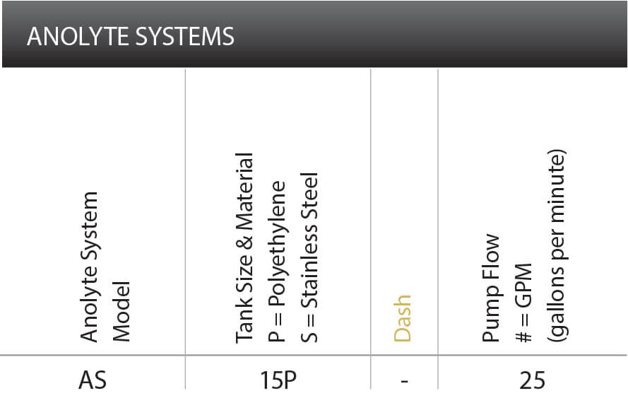
Anolyte Recirculation System
Synder Filtration’s Anolyte Recirculation System offers advanced conductivity controllers, and ultrasonic level sensors to meet the needs of both automotive and industrial E-Coat applications.
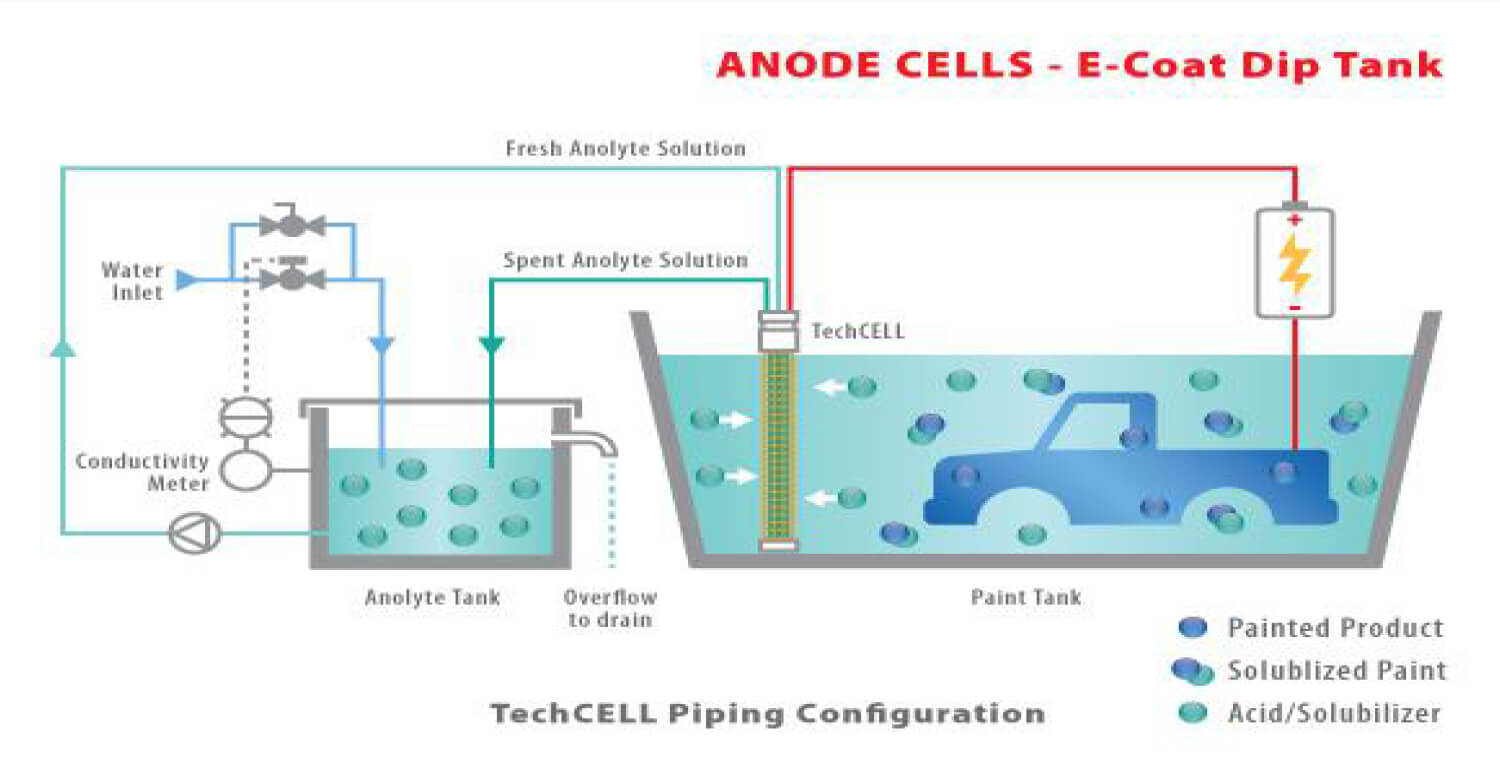
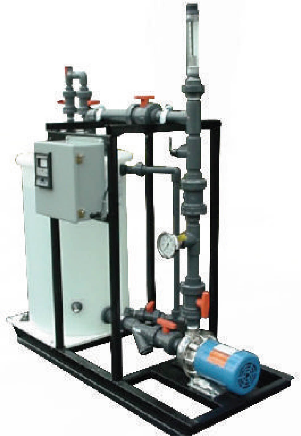
FEATURES AND BENEFITS
- Monitoring systems are capable of collecting data for showing trends and other important information
- Increases anolyte cell life by controlling and maintaining both
acid level and acid proportions in your tank - System design and parts are customizable to fit your specific
criteria and configurations.
STANDARD PARTS INCLUDED IN EACH ANOLYTE SYSTEM
- Anolyte storage tank
- Circulation pump
- Primary anolyte flow meter
- Conductivity controller and sensor
Case Studies
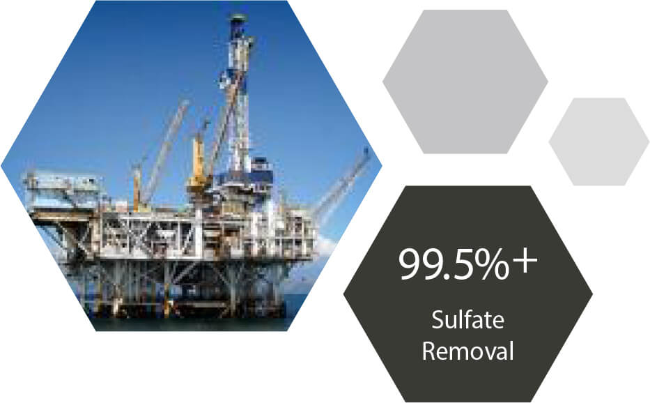
SEAWATER SULFATE REMOVAL
NFSTM NANOFILTRATION MEMBRANES
BACKGROUND
As global demand rises, Nanofiltration technology has become essential for the reduction of sulfate and enhancement of oil recovery (EOR) throughout the oil and gas industry. The objective of this study was to examine the performance of Synder’s NFSTM sulfate removal membrane against that of a leading competitor with an incoming feed stream representative of that found in the field. ASTM D1141-52 is a well-known, standard practice for the preparation of substitute
ocean water and was therefore used in this study to simulate seawater, a common feed for waterflood injection processes.
FEED SOLUTION, MEMBRANE, & OPERATING CONDITIONS
Synder’s NFSTM and a sulfate removal membrane from a leading competitor were tested in 2540 spiral wound element modules. ASTM D1141-52 synthetic seasalt was used as the incoming feed. Elements were tested at 330 PSI with a feed flow rate of 3 GPM at 25°C. Permeate flux and sulfate rejection were recorded at 0%, 25%, 50%, and 75% total system recovery.
Table 1: Operating Conditions and Membrane Specifications
| Feed Solution | |
| Material | ASTM D1141-52 Synthetic Sea Salt |
| Synder Membrane | |
| Element | NFSTM-Spiral Element |
| Membrane | Polyamide-TFC |
| Competitor’s Membrane | |
| Element | NF-Spiral Element |
| Membrane | Polyamide-TFC |
| NF Standard Operating Parameters | |
| Pressure (PSI) | 330 |
| Cross Flow Rate (GPM) | 3 |
| Temperature (C) | 20-25 |
RESULTS
The membranes were tested for permeate flux and sulfate rejection from 0 to 75% recovery. Based on the information displayed in Table 2 below, NFS displayed superior flux and overall sulfate rejection under the same conditions. The flux decay overall for NFS was also much less, at ~33%, compared to ~50% for the leading competitor.
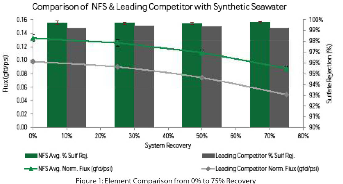
CONCLUSION
The results of this study indicate that NFS demonstrates superior sulfate rejection and flux performance versus a leading competitor in a feed stream comprised of ASTM D1141-52 synthetic seasalt. Throughout the duration of the study, NFS had an average sulfate rejection of greater than 99.5% compared to 99.2% rejection observed for the leading competitor. These results indicate that Synder’s NFS membrane is suitable for EOR techniques and sulfate removal applications throughout the oil and gas industry.
OIL REMOVAL IN WASTEWATER TREATMENT
PX ULTRAFILTRATION MEMBRANE
BACKGROUND
The removal of oils present in many industrial wastewater streams has become increasingly necessary in order to accommodate stringent discharge regulations and growing manufacturing costs. The utilization of Ultrafiltration is an effective method for achieving this separation, allowing for safe discharge or re-use. The goal of this study was to investigate the performance of Synder’s PX membrane in a representative feed stream and compare such performance to that of a leading competitor.
FEED SOLUTION, MEMBRANE, & OPERATING CONDITIONS
Synder’s PX and an oily wastewater treatment membrane from a leading competitor were tested in flat sheet form. Testing was performed at 15 PSI, at a crossflow rate of 0.5 GPM, and the system was run in total recirculation mode. Membranes were challenged with 1000ppm emulsified I-19 paraffinic vacuum pump oil, to which 500ppm sodium dodecyl sulfate was added an emulsifying agent. Flux performance was evaluated over time, and rejection was calculated via
Abs531nm.
Table 1: Operating Conditions and Membrane Specifications
| Feed Solution | |
| Material | 1,000ppm Emulsified I-19 Vacuum Pump Oil 500ppm SDS (as emulsifying agent) |
| Synder Membrane | |
| Type | PX Polyacrylonotrile-UF |
| Configuration | Flat Sheet |
| Competitor’s Membrane | |
| Type | Polyacrylonitrile-UF |
| Membrane | Flat Sheet |
| UF Operating Parameters | |
| Pressure (PSI) | 15 |
| Cross Flow Rate (GPM) | 0.5 |
| Temperature (C) | 25 |
RESULTS
Flat sheet membranes were tested in a feed stream comprised of emulsified oil, and performance was evaluated by monitoring flux Synder’s PX membrane demonstrated superior clean water flux, and, by the 90-minute mark, both membranes reached an equivalent steady state flux of 61 GFD. Rejection, calculated using UV-Vis, was determined to be >99% for both membranes.
Table 2: Performance Results
| Filtration Results | Synder PX | Leading Competitor |
| Rejection (%) | >99% | >99% |
| Jwater (GFD) | 176 | 102 |
| Joil (GFD) | 61 | 61 |
CONCLUSION
In this study, Synder’s PX membrane was evaluated for its oil retention and flux performance characteristics when challenged with a feed stream comprised of emulsified oil. The membrane of a leading competitor, designed for oily wastewater separation, was similarly evaluated. The results obtained indicate that PX is a membrane well-suited for oil removal in wastewater treatment applications, given by its competitive steady state flux and high retention characteristics, which were found to be comparable to that of the
leading competitor.
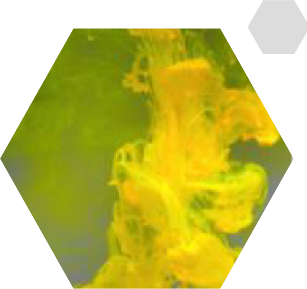
OPTICAL BRIGHTENING AGENT (TEXTILE INDUSTRY)
NFX NANOFILTRATION MEMBRANE
BACKGROUND
 Optical brightening agents are special dyes that absorb ultraviolet light and re-emit light in the blue region, usually at 420 – 470nm. This
application is called the “whitening effect”, which is commonly used to enhance the appearance of certain colors without the damaging effects of bleaching.
By increasing the amount of blue light reflected, yellow tones appear whiter. Membrane technology can be applied to capture and concentrate the optical brightening agent for reuse to lower the operating cost in textile and paper industries. Membrane technology provides a process of simultaneous concentrating
and desalinating dye solution and thus obtaining concentrated dye with low salt content.
FEED SOLUTION, MEMBRANE & OPERATING CONDITIONS
An optical brightening agent was used to test the feasibility of using Synder’s NFX (TFC 150-300Da) Nanofiltration membrane to concentrate the dye for reuse.
Table 1: Operating Conditions and Membrane Specifications
| Feed Solution | |
| Material | Optical Brightening Agent |
| Molecular Weight (Da) | 430 |
| Dye Manufacturer | JiNing XinHui Chemical Industry CO. LTD. |
| Membrane | |
| Element | NFX-Spiral Element |
| Membrane | Polyamide-TFC |
| NF Standard Operating Parameters | |
| Pressure (PSI) | 110 |
| Temperature (C) | 20-25 |
RESULTS
 Comparison between the concentrate (A), permeate (B) and feed solution (C) at the end of the experiment. Test Results. In a single batch process, the initial volume was concentrated by a factor of 2 while achieving a rejection rate of greater than 99%. The effectiveness of the NFX membrane in concentrating this dye is represented visually in a side-by side comparison (Figure 1), where the difference between permeate (B) and concentrate solution (A) is clear. The results of the filtration are summarized in Table 2.
Table 2: Performance Results
| Results | |
| Dye Rejection | >99% |
| Average Permeate Flux (GFD) | 9.4 |
| Final Salt Rejection (%) | 22.4% |
CONCLUSION
The NFX membrane was effective in concentrating the optical brightening agent. The steady state permeate flux was 9.4 GFD, with a 49% decline over the entire batch process. The NFX membrane exhibited a low salt rejection, which is ideal for improving the quality of dye solution during the concentration
process. Thus, the implementation of the NFX membrane has the potential to reduce the capital costs associated with textile manufacturing and give plants an increased ability to meet discharge regulations.
DISSOLVED NATURAL ORGANIC MATTER RECOVERY
NFX NANOFILTRATION MEMBRANE
BACKGROUND
Surface water may have high levels of dissolved organic matters (DOM) in many parts of the world. In many cases, DOM must be removed via chemical flocculation and/or coagulation from water before use. With the help of Nanofiltration technology, DOM can also be separated and purified into a natural additive for fertilizers to improve the structure of soil and enhance the nutrient acceptance level by a wide variety of plants.
In this specific case, a customer was seeking an energy-saving technology to concentrate the DOM from a swamp in Georgia. Obviously, the more concentrated the humic acid is in the final product, the higher the value and the greater the savings in transport costs. Synder’s NFX membrane was tested in a two month field trial and resulted in a concentration factor of up to 100x, making NF technology a viable solution to achieve the concentration goal.
FEED SOLUTION, MEMBRANE & OPERATING CONDITIONS
Table 1: Feed Solution, Membrane, & Operating Conditions
| Feed Conditions (River) | |
| Conductivity (us/cm) | 85 |
| pH | ~6 |
| Absorption without pH adjustment | 0.516 |
| Turbidity (NTU) | 2.82 |
| Beginning Volume (gal) | 600 |
| Membrane | |
| Element | NFX-2-2540HM Spiral Element |
| Membrane | Polyamide-TFC |
| NF Standard Operating Parameters | |
| Pressure (PSI) | 110 |
| Temperature (C) | 20-25 |
RESULTS
The NFX permeate was plotted over the course of concentration from concentration factor of 1 to 125. The initial permeate flux was at 55 GFD, and the permeate flux at a concentrate factor of 116 was 15 GFD. The overall flux declined 70%, but the flux was highly recoverable via cleaning with acid cleaner and alkaline detergent.
The NFX membrane was able to concentrate the materials progressively and the permeate appears to be clean even when the product was highly concentrated by more than 100 fold.
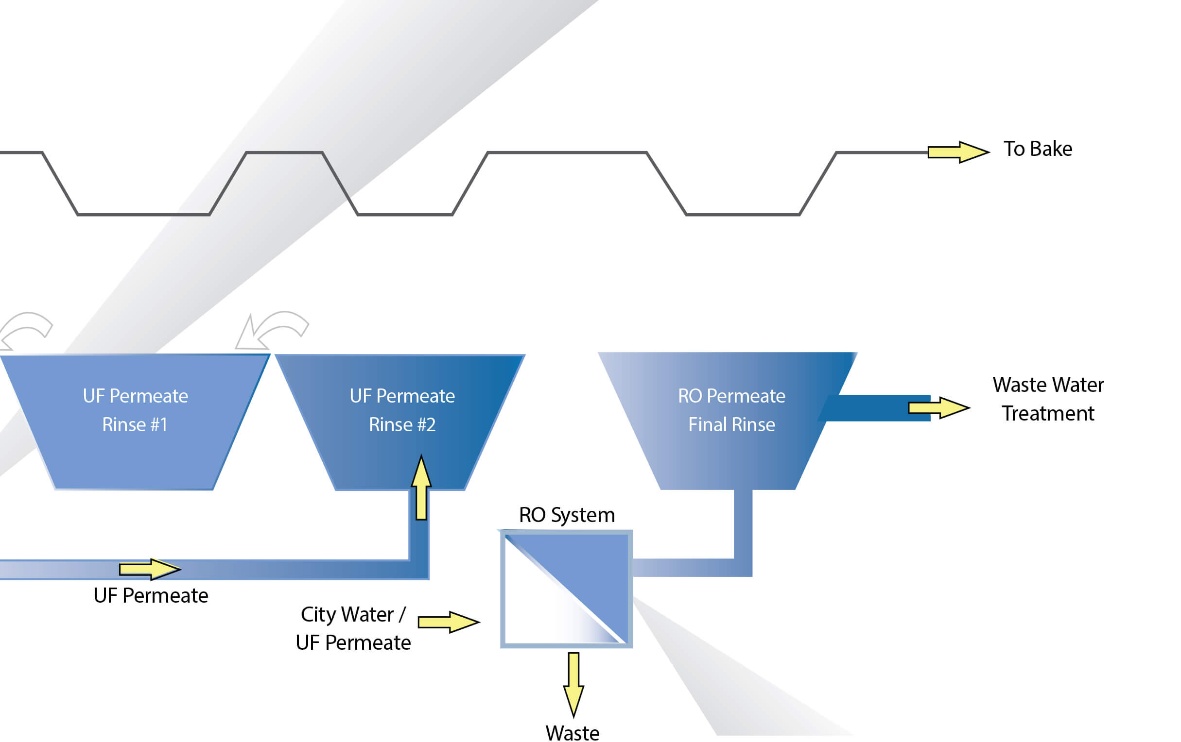
E-COAT PAINT: UF PERMEATE RECOVERY
SYNDER UF MEMBRANES
BACKGROUND
Cathodic paint is used in electrocoating processes to create a corrosion resistant film on the exterior of metal products. These products are submerged in paint baths and painted via electrophoretic deposition. After painting, products are submerged in rinse tanks, causing overflow into the paint baths.
It is essential to combat paint dilution and maintain stable paint concentration, otherwise coating and corrosion resistance may be compromised. Ultrafiltration membranes are the industry standard for both concentrating cathodic paint and generating water for the initial rinse stages. UF membranes should pass less than 0.3% solids for an acceptable concentration, sufficiently clean permeate, and effective pretreatment for Nanofiltration or Reverse Osmosis systems. Synder’s V4, V5, and V6 PVDF UF membranes were tested for their performance in concentrating and recovering cathodic paint. The experiment was conducted on a single cell cross-flow filtration unit with a micro-pump. The paint tested was supplied directly from the manufacturer.
FEED SOLUTION, MEMBRANE & OPERATING CONDITIONS
Table 1: Feed Solution, Membrane, Operation Condition
| Feed Solution | |
| Material | Cathodic Paint |
| Dry mass (wt/wt) | 12.8% |
| Membrane | |
| Type | V4, V5, V6 |
| MWCO | 70, 200, 500 kDa |
| Material | PVDF with Surface Treatment |
| Operating Parameters | |
| Inlet Pressure (PSI) | 60 |
| Temperature (°C) | 19-27 |
| Crossflow Rate (GPM) | 0.9 |
RESULTS
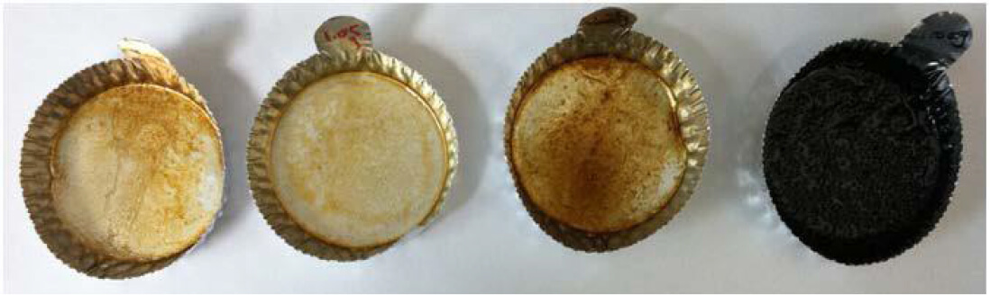
The dry mass in the permeate from the UF membranes is listed in Figure 1. The results show that both the V4 and V5 membranes passed less than 0.3% dry mass, which meets industry standards. The average flux of the V5 and V6 was approximately 18 GFD while the flux of the V4 was approximately 16 GFD. Based on the small amount of dry paint mass in the permeate, both the V4 and V5 membranes are suitable for cathodic paint recovery.
Figure 1: Percentage Dry Mass in Permeate
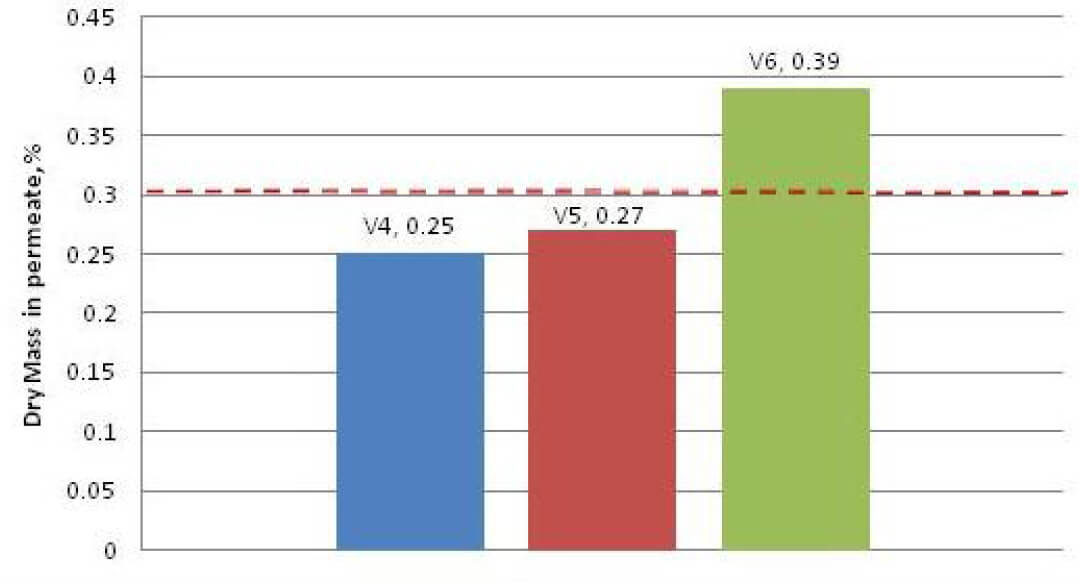
Figure 2: (Left to Right) Permeate samples from the V4, V5, V6 membranes, and feed.
Feasibility Testing
In addition to performing case studies, Synder Filtration offers a wide array of feasibility testing options for our customers. With our newly designed research & development laboratory and fleet of pilot systems, we are able to conduct feasibility tests both in-house and on-site. We strive to gain a better understanding of your process goals in order to develop a comprehensive testing plan to suit your separation needs. The ultimate goal is to provide meaningful trial data toward the design, fabrication, and successful implementation of a commercial scale system.

1. CUSTOMER SUBMITS PILOT STUDY RFQ FORM. This helps us to gather important information about the feed stream, operating parameters, and the customer’s application goals.
2. RFQ REVIEW. Synder account manager schedules review meeting with the customer and the engineering staff to discuss the project and clarify any remaining questions.
3. FEASIBILITY TESTING. A feasibility test is proposed to the customer, and conducted if approval is received. A feasibility report is prepared with 24-48 hours after test completion.
- Flat sheet feasibility tests: Synder’s complete line of NF, UF, and MF and MAX membranes are available in a variety of different flat sheet options for feasibility testing.
- Spiral element feasibility tests: In some cases such as feed streams requiring high operating pressure to obtain additional concentration and flux data, spiral elements may be recommended for use on feasibility tests.
- Analytical capabilities include TOC levels, COD levels, hardness, chloride, sulfate, and iron concentrations, liquid viscosity, turbidity, pH, and conductivity measurements. Synder is also able to outsource other analytical instruments such as SEM, FTIR, BOD, TSS, and other ion measurements if the customer accepts 3rd party involvement in the testing.
4. PILOT STUDY TESTING. If feasibility results are positive, a pilot study is proposed. Pilot studies can last anywhere from one week to several months or longer, depending on the nature of the application and possible variability in the feed stream.See pilot system specs.
5. FULL SCALE SYSTEM DESIGN & FABRICATION. If the pilot study results are positive, a full scale system is proposed and revised as needed until the customer is satisfied with the design specs, lead time, and projected ROI. Synder then fabricates the system.
6. SYSTEM INSTALLATION & COMMISSIONING. The final step is installation, commissioning, and training on site. Start up and commissioning service can be done worldwide.
Membrane Housing & Spare Parts
Synder Filtration stocks large inventories of accessories and spare parts required for membrane installation and operation. Contact us to find the right parts for your membrane processes. We also provide custom sanitary and industrial stainless steel housings for UF and MF systems.
STANDARD HOUSING AND PARTS
| Parts | Material |
| Top Cap | Stainless Steel |
| Tri Clamp | Stainless Steel |
| Victaulic Clamp | Stainless Steel |
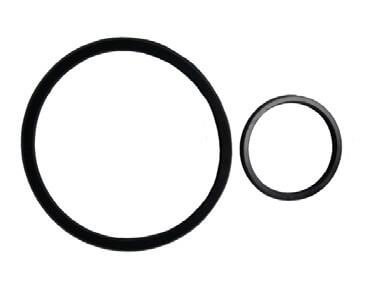
| Gaskets | EPDM, Viton |
| O-Rings | EPDM, Viton |
| Bottom Cap | Stainless Steel |
NOTE: Contact Synder for specific part numbers and other items not listed.
SS SANITARY HOUSING FOR UF/MF SYSTEMS
| Specifications | |
| Material | SS304 & SS316 |
| Size | 6″ & 8″, other sizes available upon request |
| Pressure Range | 150 to 600PSI |
| Surface Roughness | Interior – RA = 0.4um or above Exterior – RA = 0.8um or above |
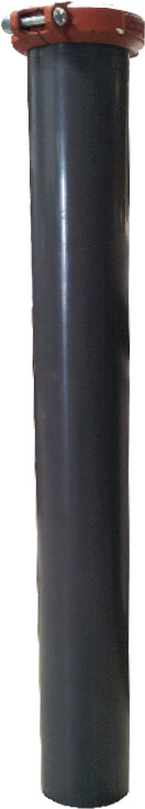
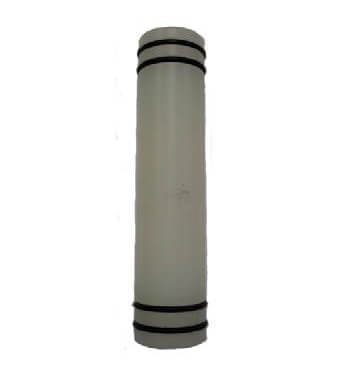
PVC HOUSING
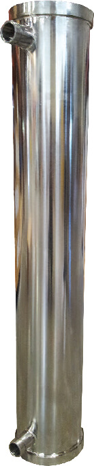
STAINLESS STEEL HOUSING
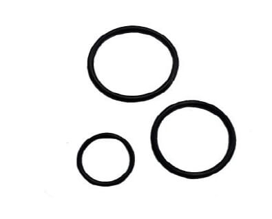
O-RINGS
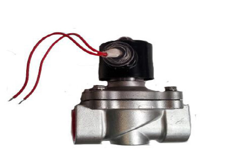
SOLENOID VALVE
L-SEALS
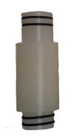
INTERCONNECTOR
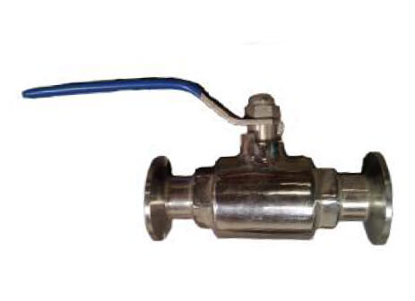
STAINLESS STEEL BALL VALVE
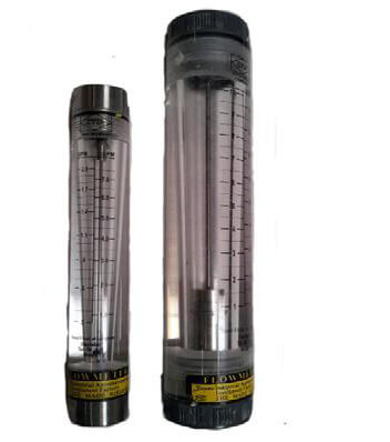
FLOW METER
PERMEATE ADAPTER & END PLUG
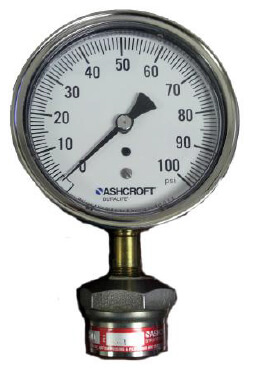
PRESSURE GAUGE
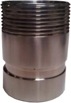
NIPPLE CUT WITH GROOVE
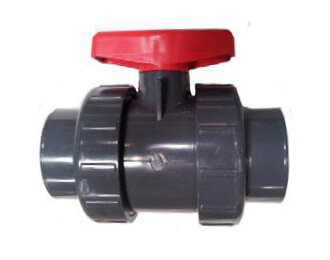
PVC BALL VALVE
Additional UF Housing & Anolyte Spare Parts
Synder Filtraton stocks large inventories of spare parts and accessories for the E-Coat industry. With a wide range of spare parts and accessories for anolyte and membrane filtration systems, Synder can supply or replace these accessories with exceptional speed so your production is minimally stalled. We can also provide industrial grade housing units for our elements, which can be customized to fit any system. Contact us to find the most appropriate housing unit and parts for your E-Coat line.
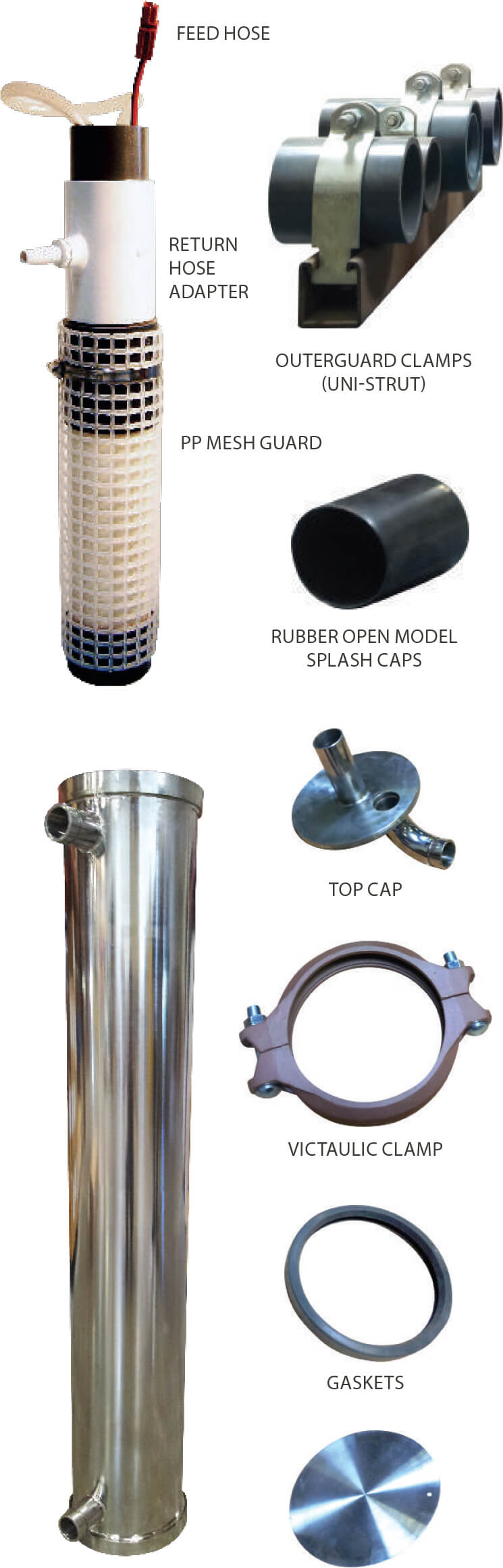
ANOLYTE SPARE PARTS
| Anode Cell Splash Caps |
| 1.5” T150G |
| 1.5” TCX150G |
| 2.0” T200G |
| 2.0” TXC200G |
| 1.5” Polypropylene Mesh Outer Guard |
| 2.0” Polypropylene Mesh Outer Guard |
| Outerguard Clamp T150 |
| Outerguard Clamp T200 |
| 3/8” PVC Feed Hose |
| 1/2” PVC Feed Hose Adapter |
| Return Hose |
| Return Hose Adapter |
| Anderson Power Pole w/ 7″ Lead Wire |
UF HOUSING AND PARTS
| Parts | Material |
| Top Cap | Stainless Steel |
| Tri Clamp | Stainless Steel |
| Victaulic Clamp | Stainless Steel |
| Gaskets | EPDM, Viton |
| Bottom Cap | Stainless Steel |
| Model | Housing Unit | Material | Port-to-Port Length | Total Length |
| 2” | IH2519RF IH2540 |
SS316 SS316 |
21.84” (555mm) 42.60″ (1082mm) |
26.23” (666mm) 48.88″ (1242mm) |
| 4” | Ih6030 Ih6042 Ih60RF IHKR4 |
PVC PVC PVC PVC |
31.63” (804mm) 42.00” (1067mm) 49.63” (1260mm) 37.00” (940mm) |
37.88” (962mm) 48.25” (1226mm) 55.75” (1416mm) 43.25” (1099mm) |
| 6” | IH60A IH60RF IH60RF-M3 |
PVC PVC PVC |
43.00” (1092mm) 49.63” (1261mm) 49.63” (1261mm) |
50.80” (1290mm) 55.75” (1416mm) 57.13” (1451mm) |
| 8” | IH80C IH80D IH80E IH80SB IH80S/SM |
PVC PVC PVC SS304 SS304 |
43.00” (1092mm) 51.03” (1296mm) 43.00” (1092mm) 43.00” (1092mm) 51.03” (1296mm) |
51.75” (1314mm) 56.75” (1441mm) 51.75” (1314mm) 50.63” (1286mm) 56.75” (1441mm) |
NOTE: Contact Synder for specific part numbers.
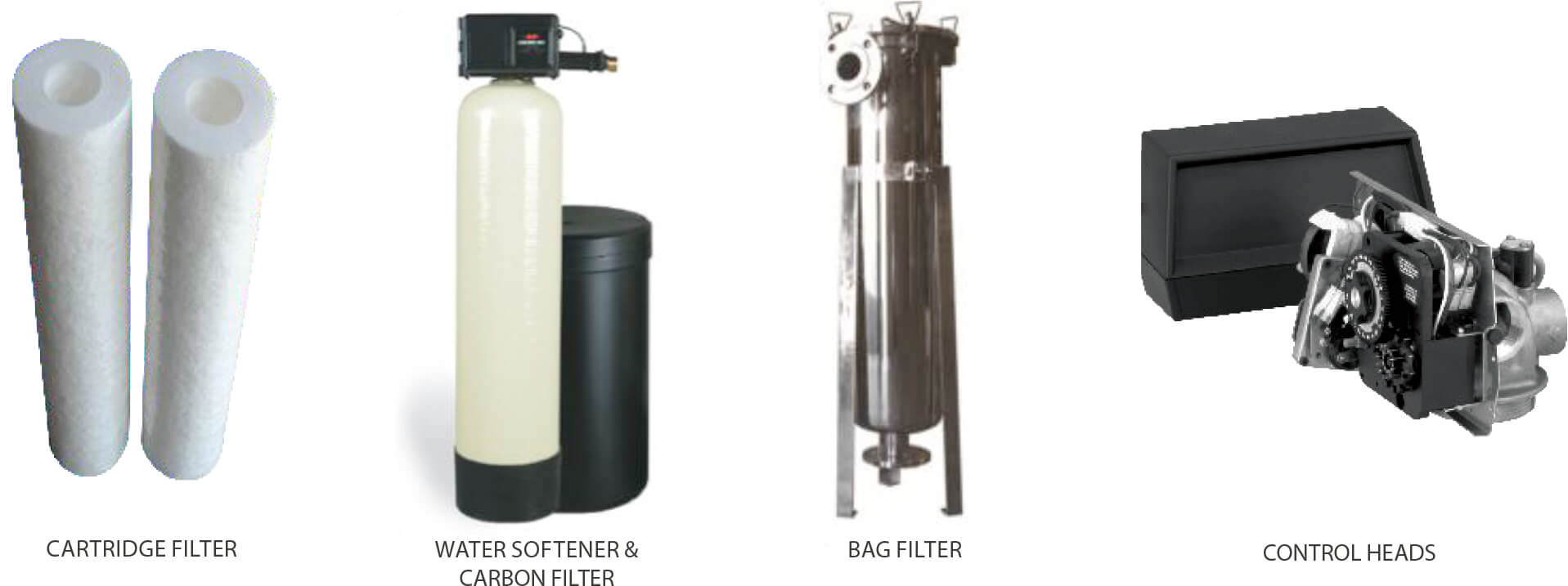
Pretreatment Products
Synder Filtration offers a wide range of pretreatment options to help maintain membrane life and sustain performance. Ranging from cost-effective bag filters to large volume multimedia filters, Synder’s pretreatment products are engineered to reduce the amount of chemical constituents and particulate matter that can foul membranes. Contact us today to learn about the right pretreatment options for your application.
CHEMICAL DOSING
Small peristaltic pumps constantly deliver low concentrations of antiscalant, antioxidant (for chlorine), pH balance (acid/caustic), or other pretreatment chemicals to ensure optimal membrane performance.
CARTRIDGE FILTERS
Cartridge filters are a good “final catch” before the membrane. Cartridge filters from 0.1-100micron are available.
WATER SOFTENERS
Synder Filtration’s water softeners are designed to remove inorganic ion species from the feed solution via ion exchange resin loaded into a tank with a recharge control head and backflush capabilities.
BAG FILTERS
Bag filters are a cost effective method of reducing particulates in feed streams, resulting in an increase in membrane life and performance. Bag filters from 0.1-100 micron are available.
ACTIVATED CARBON FILTERS
Granular Activated Carbon (GAC) is excellent for removing organic solvents in water, including chlorine.
MULTI-MEDIA FILTERS
Multi-Media filters are an optimal choice when dealing with large volumes of TSS & turbidity.
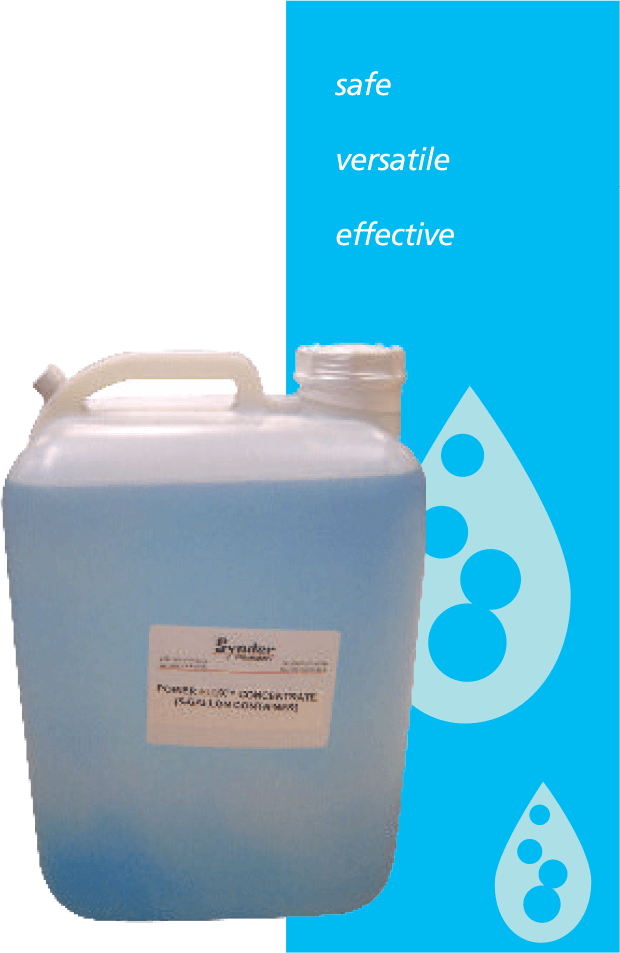
Cleaning & Dosing Chemicals

Ultrafilter Cleaning Solution for Electrocoating
The Power Flux Concentrate (PFC) cleaning solution was formulated specifically for removing paint solids from Synder’s V6 E-Coat membranes. Formulated for normal paint fouling, PFC contains zero VOCs and unlike other UF cleaners, it only requires the addition of acid and clean water (RO or DI quality).
- Available in 1 & 5 gallon containers
- No expensive additional additives required for normal UF cleaning
- Specialized cleaning formulations available upon request to combat specialized fouling
- Biological
- Iron Heavy
- Metals
MEMBRANE CLEANER PRODUCTS
Synder offers a set of concentrated membrane cleaner products, available in liquid and powder form. The typical use concentration is a 1% solution, providing a cost effective dilution when compared to other products. The non-oxidizing biocide, Excide™ 20, is an EPA registered antimicrobial for use on membrane systems.
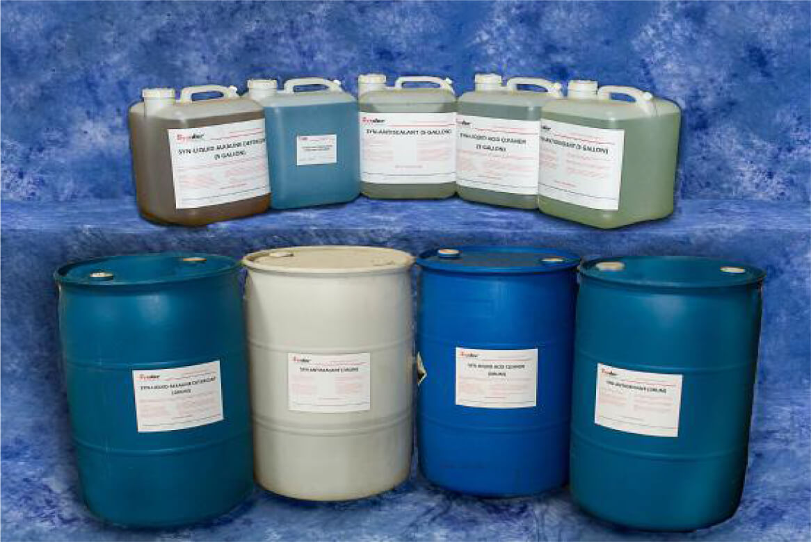
| Product | Form | pH at 1% | Foulants | Membrane |
| S-20 | Acid Powder Cleaner | 2.0 | Hardness scale, Metals, Silica | All Types |
| P-11 | Alkaline Powder Detergent | 10.7 | Silt, Organics, Biological | Polyamide-TFC, Polysulfone |
| H-50 | Liquid Acid Cleaner | 2.2 | Hardness scale, Metals | All types |
| K-12 | Liquid Alkaline Detergent | 11.5 | Silts, Organics, Biological, and Sulfate deposits | Polyamide-TFC, Polysulfone, PVDF |
| Excide™ 20 | Liquid Biocide | n/a | Bacteria, Fungi | All Types |
Industrial Element Installation Procedures
PRE-INSTALLATION NOTES
Spiral elements must fit snugly in their vessels in order for them to function properly. If a loose-fitting element is put into operation, unnecessary bypass flow and lower flux may be observed.
A preservative solution is used to prevent microbial growth and membrane dry-out during shipping and storage. While this solution is not classified as hazardous, extra care should be take to limit exposure.
Recommended Equipment:
- Sharp knife or scissors
- Gloves
- Safety glasses
- Dust mask
INSTALLATION PROCEDURES
- Remove the element from the plastic bag and take this opportunity to do a thorough visual examination of the element. There should be no mold, dust, or dirt anywhere on the element.
- Prepare an element loading diagram to document the serial number(s), date, element model number, location within the system, and any other required information for future reference.
- Install the new O-ring supplied with your element onto the top cap and lubricate them with glycerine. A vial of glycerine is included with the shipment.
- Insert the element into the pressure vessel. It should fit snugly.
- O-rings should be well lubricated prior to installation with a non-petroleum based lubricant such as glycerine or any mild household liquid detergent.
- A sufficient flush should be performed on all elements prior to start-up. Clean water at 122°F (50°C) should be used in a non-recirculating mode for at least 10 minutes after installation. This should remove residual preservative solutions, and glycerine.
- The element is now ready for start-up. Feed and/or recirculation pumps should “ramp-up” RPMs slowly to prevent the element from being shocked. Varial Frequency Drives (VFDs) are recommended for all feed and recirculation pumps to safely control pump RPMs.
- Synder Filtration recommends the collection of daily performance data of the system and element performance. The following data should be collected at least daily and is required in the event of a warranty claims:
- Flows (feed, permeate, concentrate)
- Pressures (feed, permeate, concentrate)
- Operating temperatures (production and CIP)
- Hours of operation (production and CIP)
- Other cleaning parameters (pH, time, chlorine PPM exposure)
- Unexpected events (system upsets, unscheduled shutdowns, etc)
E-Coat Element Installation Procedure
- Remove the flow meter/assembly from the housing top cap. Store in a safe place to prevent damage.
- Remove the Victaulic coupling from the top cap.
- Lift the top cap off the housing. In most cases, the element will lift up with the top cap. If it does not, pull the spent element out by the permeate tub extension, ATD, or by removing the housing and bottom cap to push the element out.
- Carefully remove the element from its storage bag. For elements with rubber seals, ensure they are properly installed by lubricating with glycerine.
- Replace the O-ring on your top cap with the new O-ring supplied with your element and lubricate them with glycerine. A vial of glycerine is included with each shipment.
- Eliminate the residual paint from the housing. Fill the housing approximately 1/3 full with DI/RO water.
- Insert the bottom plug into the end of the element without the rubber seal(s). For elements with no rubber seal, insert bottom plug into any end.
- Insert the element into the housing, bottom end plug first. Do not force the element. For elements with tape wrap, you may trim the tape until it has a snug fit.
- Gently push the element to make sure the element is seated on the bottom of the housing. Ensure the permeate tube is completely submerged in DI/RO water.
- Carefully insert the top cap connector into the permeate tube. Replace the top cap and tighten the bolts. Reinstall the flow meter/bypass assembly and tighten the union connections.
- Circulate DI/RO water through the element for 15 minutes in the CIP loop. Purge to drain, and then refill with fresh DI/RO water. If this is not possible, soak the element in DI/RO water for at least one hour, purge to drain, and re-fill the housing with fresh DI/RO water.
- Open both the paint permeate to rinse valve and the paint return valve.
- Start paint feed pump and slowly open paint feed valve (to fully open in 3-5minutes). Adjust the inlet pressure to a minimum of 50 PSI.
Warning: When operating on paint or cleaning, the appropriate permeate transport valve must be 100% open. When operating on paint, the “Permeate to Rinse” valve must be 100% open. When cleaning, the “Permeate to CIP tank” valve must be 100% open. Throttling or closing any
permeate valve while the element is in operation can result in “leakers” and “smokers” and will void our warranty. - Adjust the pressures until the system balances out and the pressure/flow rates stabilize.
Disclaimer: Procedures may not apply to all E-Coat processes. Please contact Synder for more information on proper handling and storage guidelines.
TechCELL Installation Guide
GATHER THE FOLLOWING TOOLS PRIOR TO STARTING:
- DI Water source, the cells will need to be filled as they are placed into the paint bath
- Utility Knife
- Qty 2 1/2” wrenches
- Qty 2 9/16” wrenches
INSTALLATION WITH PAINT IN THE TANK
- Carefully remove the TechCELL shell from its packing, leaving on the plastic bag containing the TechCELL.
- Wipe off the surface of the anode for the TechCELL and remove tape from the anolyte supply tube. DO NOT USE SUPPLY TUBE TO HOLD ANODE.
- Install the short Power Cable to the anode tap with the supplied hardware.
- Carefully insert the anode into the TechCELL shell. Lay shell on a flat, clean area. Start by sliding the anode in the open top of the shell. Once the anode is completely inserted, lift top of the shell no higher than a 45-degree angle and rotate the shell to allow the anode to slide into the remainder of the way in the shell.
- Carry the TechCELL to the paint tank. Remove the protective plastic bag from the TechCELL.
- Gather the 2 sets of Unistrut cell clamps for one TechCELL.
- Lower the TechCELL into the paint bath close to the designated position.
- Place the clamps around the neck of the TechCELL. The TechCELL should be vertically positioned so that the membrane is completely submerged just below the paint level.
- Once the TechCELL is secured immediately fill the TechCELL with DI water to a level a few inches below the return nozzle.
- Attach the 3/8” supply line to the flow indicator after the proper length of the tubing has been determined and trimmed.
- Determine the proper return tubing length. Attach the 1/2” return line to the TechCELL and then insert the other end into the return manifold.
- Attach the long power cable to the short power cable. Connect the power supply cable from rectifier to the anode cell power cable (with quick connect).
INSTALLATION WITHOUT PAINT IN THE TANK
- Follow the above steps, but do not remove the protective plastic bag from the membrane area. Typically the bag is lowered to a point on the cells neck where interference with the clamps is eliminated.
- Once the cell is in place; fill the TechCELL with DI water until the paint is being introduced into the tank. Do not let the anolyte (DI) solution in the cells remain dormant for more than 24 hours. Verify that the anolyte circulation system is operational prior to installing the TechCELL units.
FLOW INDICATOR INSTALLATION
Install by tapping a 1/4” NPT in supply manifold. Install indicator using Teflon tape around threads. Flow indicators should be vertical on the manifold.
POWER CABLE INSTALLATION
- Attach the lug connector to the buss bar in a location that allows multiple TechCELL long Power Cable connections. Typically one every 5 feet on the buss bar is adequate.
- Install the long Power Cables to the lug. Typically five Power Cables per 125 Amp lug.
Anode Cell Removal and Maintenance
To remove the cell for maintenance, inspection, replacement or long term storage, please do the following:
- Make sure all power from rectifier is turned off and rectifier locked out. Never work on an energized system.
- Shut off and disconnect the anolyte supply tubing from the secondary flow indicator.
- Unplug the quick disconnect power lead and disconnect the short cable from the anode.
- Remove the anode from the cell.
- Remove the anolyte return tubing from the nozzle on the cells neck.
- Loosen and remove the cell clamps from the strut channel, while holding the shell from falling into the tank.
- Carefully lift the shell out of the tank. When about 1/3 to 1/2 of the shell is out of the tank, start rotating the shell to allow the anolyte solution to drain into the paint bath.
- Once the shell is out of the tank, immediately rinse off the shell with DI water to remove any paint. Resins and solids may be removed with solubilizer and or diluted solvents.
- Do not allow membrane to dry out. If it is necessary to store the shell for an extended period of time, place unit in a plastic bag and seal it from the environment. A small amount of biocide placed in the bag will aid in unwanted growth. Store unit vertically when possible.
CELL REPLACEMENT
- Carefully insert anode assembly into the shell, be sure the anode is fully sealed.
- Work backwards through steps 1-6, making sure all power from rectifier is turned off and rectifier locked out.
Standard Cleaning Guidelines
The following procedure is a general guideline for the cleaning/sanitization of spiral elements. Depending on individual process streams, equipment and process time some variations in cleaning procedures may be required for optimal cleaning results. Please consult a qualified chemical supplier for application specific cleaning regimes.
Improper cleaning sequence, chemical concentration or abnormal temperatures/pH/pressure profiles can significantly reduce membrane life and possibly void any warranties offered on the element(s). If you have any questions or concerns about your cleaning regime, please contact Synder Filtration immediately.
CONCENTRATE DISPLACEMENT AND INITIAL FLUSH
- Flush the remaining concentrate in the system back to the concentrate tank or to drain.
- Using clean water heated to 122°F/50°C (or 104°F/40°C for NF), adequately flush the system in non-recirculation mode to remove any
remaining build-up. The retentate and permeate should appear to be clean after this step. - Perform a complete Clean-In-Place (CIP) immediately after the initial flush per the following.
CAUSTIC WASH
- Circulate warm clean water (122°F/50°C or 104°F/40°C for NF) through the system under standard pressure and flow parameters.
- Add caustic SLOWLY to achieve a pH of 10.8-11.0. DO NOT EXCEED pH 11.0 (pH 10.5 for NFW/NFG/PZ/PY/PX).
- Circulate caustic solution for 30 minutes.
- Flush the system to drain with clean, warm water (same temperature as before).
ACID WASH
- Circulate warm clean water through the system under standard pressure and flow parameters.
- Add a sufficient amount of acid SLOWLY to achieve a pH of 2.0-2.2. DO NOT EXCEED pH 2.0 (pH 3.0 for NFW/NFG/PZ/PY/PX).
- Circulate acid solution for 30 minutes.
- Flush the system to drain with clean, warm water (same temperature as before).
SANITATION (CAUSTIC/CHLORINE SOLUTION) – FOR UF/MF
- Circulate warm clean water through the system under standard pressure and flow parameters.
- Add caustic SLOWLY to achieve a pH of 10.8-11.0. DO NOT EXCEED pH 11.0 (pH 10.5 for PZ/PY/PX).
- Add chlorine SLOWLY to achieve constant level of 150 ppm. DO NOT EXCEED 180 ppm.
- Circulate the caustic/chlorine solution for 30 minutes.
- Periodically check and maintain a chlorine concentration of 150 ppm.
- Flush the system to drain with clean, warm water (same temperature as before).
Note: For NF, dechlorination is recommended.
Synder Filtration believes the above information and data herein to be accurate. However, said information is offered in good faith, but without guarantee of results since the conditions and methods used are beyond Synder Filtration’s control. Synder Filtration assumes no liability as to the application of the previously mentioned data.
E-Coat Cleaning Guidelines
Spiral Elements should be cleaned when the permeate rate has declined between 20-30% from the steady state permeate rate that was recorded when either the element was installed initially or last cleaned. Steady state permeate rate is the rate that you record about 15-20 minutes after the element is initially put on the paint, or after the element has been thoroughly cleaned.
Note: The permeate rate should never drop more than 30% before an element is cleaned.
CLEANING PROCEDURES
- When initially cleaning an element, flush the paint from the element (preferably back to the paint tank) with UF permeate. If your system is
large enough, and time permits, do this 2 more times. This helps with the cleaning process and helps recover as much paint as possible. - If UF permeate is unavailable, make up a solution of artificial permeate using DI/RO water and acetic acid. Adjust the heat and pH of the
solution to that of the paint. Flushing the paint from the element with cold DI/RO water, you can “set” the paint on the element surface,
making it difficult to clean. Confirm that this is acceptable with the paint manufacturer before proceeding. - After flushing the paint from the element, flush the element to drain. Start with a full heated cleaning tank of DI/RO water, pH adjusted to pH
of the paint. Once you have started flushing the element to drain, open the DI/RO water fill valve to the cleaning tank to maintain the level in
the cleaning tank. This will allow you to thoroughly flush the element to drain, while gradually lowering the temperature of the water. - When the flush water is reasonably clean from the element , slowly close the cleaning pump discharge valve and stop the pump.
SPECIAL RECOMMENDATIONS
There are many cleaning formulas available for cleaning spiral elements. Many of them were developed in the early days of cathodic paints when the paints were formulated with lead, solvents, and higher solids. These formulas were very effective for those paints, but are not as effective with today’s low solvent and no solvent, low lead and no lead paints.
Synder Filtration has formulated a concentrated cleaning product for use with our membranes and other spiral elements. The concentrate ratio is 1:99 and does not require the use of any solvents; it uses muriatic acid (acetic and formic acid may be substituted for muriatic) and is usually effective in 60 minutes or less. The key to its success is cleaning at a pH of 2.0 to 2.2, maintaining a temperature between 100°F and 110°F, and
cleaning before the permeate rate has decline too far.
For more information regarding cleaning procedures for E-Coat elements, please contact Synder.
Element Storage Procedures
6 MONTHS OR LESS (SHORT TERM)
Immediately following the final CIP flush, the system should be filled with 1% Sodium Metabisulfite (MBS) solution with a pH of 4.0-5.0. Every 7-10 days the following procedure should be performed:
- Drain MBS solution from the system and flush to drain with clean water.
- Run a caustic wash (pH 10.8-11.0; 120 – 122°F; 15-20 minutes)
- Flush to drain with clean water.
- Recharge the system with a fresh bath of MBS.
LONGER THAN 6 MONTHS (LONG TERM)
A long term shutdown (over 6 months) can be handled easily and efficiently. This involves the removal of elements from the system, soaking them in preservative solution (vertically if possible), and sealing in a plastic bag for future use.
- The preservative solution should include:
- 20% Glycerine
- 2% Sodium Metabisulfite
- pH 4.0-5.0
- Remove the element from the vessel, drain the elements in a vertical position to avoid extensive dilution of the preservative solution.
- Place the element in a preservative for a minimum of 15 minutes.
- Depending on the number of elements, the preservative solution may become diluted. In that event, add more preservative to maintain pH 4.0-5.0.
- Remove the element from the preservative and allow to drain for approximately 10 seconds, then place the element back in the bag.
- Seal the bag either via heat seal or waterproof tape. This should be done well to prevent any leakage during storage/transport.
- Element storage in 50°F – 59°F (10°C – 15°C) will increase storage life of the elements. Refrigeration is highly recommended.
- Contact Synder Filtration prior to storing any elements to discuss element warranty concerns.
Synder Filtration believes the above information and data herein to be accurate. However, said information is offered in good faith, but without guarantee of results since the conditions and methods used are beyond our control. Synder Filtration assumes no liability as to the application of the previously mentioned data.
Water Quality Guidelines
The quality of water used for flushing and cleaning Synder Filtration membranes is of utmost importance in order to avoid unwanted deposits on the membrane originating from the water. In most cases, municipal water does not qualify as “clean water”.
Special attention should be paid to possible foulants such as iron, manganese, and silicates. Clean water must meet the following specifications at all times:
| FOULANT | REQUIREMENT |
| Iron (Fe) | <0.05ppm |
| Manganese (Mn) | <0.02ppm |
| Silicate (SiO2) | <5ppm |
| Aluminum (Al) | <0.05ppm |
| Hardness | <85ppm as CaCO3 |
| Particle Size | <10 micron |
| Turbidity | <1 NTU |
Spiral Element Template
| Company: | Email: |
| Contact Person: | Address: |
| Telephone: | City/State/Zip: |
| Fax: | Country: |
ELEMENT CHARACTERISTICS
| Element Model #: (Sample: NFX-2-4040HF or DK- 4040FF) |
| Spacer Size (mil): |
| Membrane Type/MWCO: |
| Outer Wrap (FRP Hardshell, Net, or Tape): |
| Net Outerwrap Thickness (If applicable): |
| A – Element Outer Diameter: |
| B – Element Length: |
| C – Permeate Tube Material: |
| Permeate Tube Inner Diameter (Female): |
| Permeate Tube Outer Diameter (Male): |
| D – Tube Extension Length (Male): |
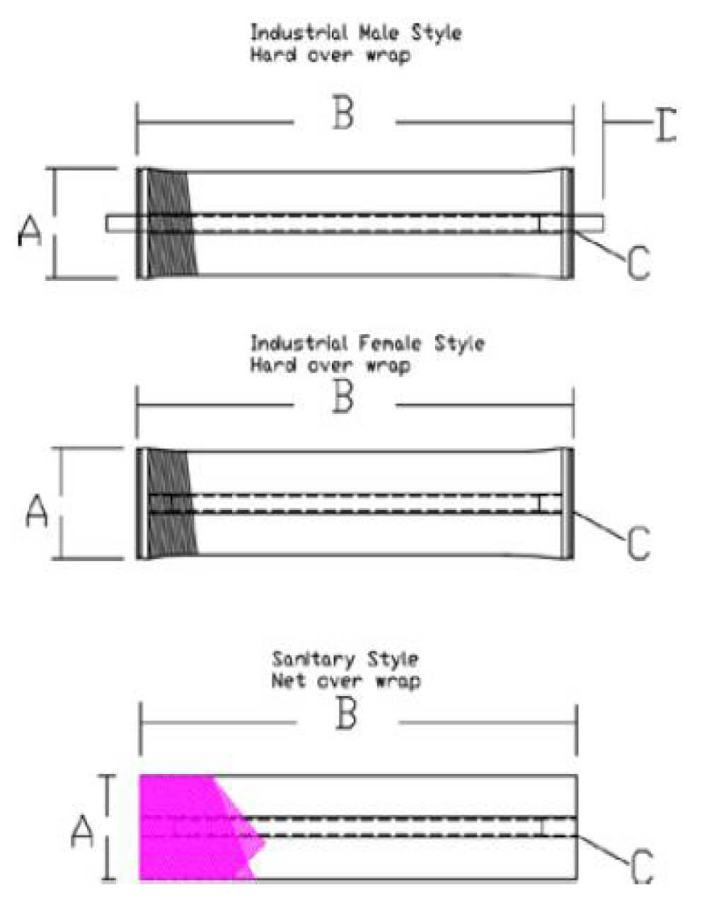
TechCELL Drawing
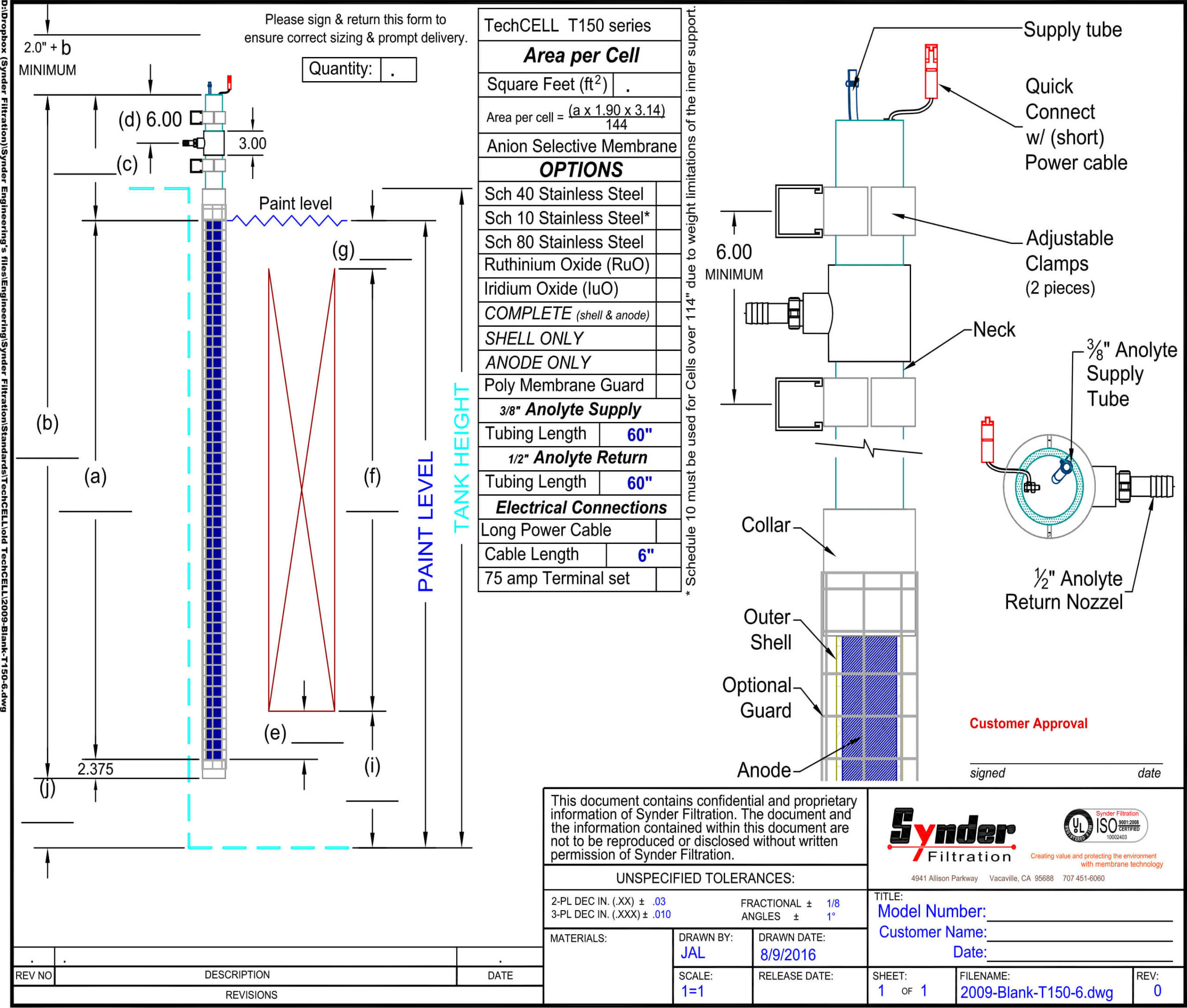
SuperCELL Drawing
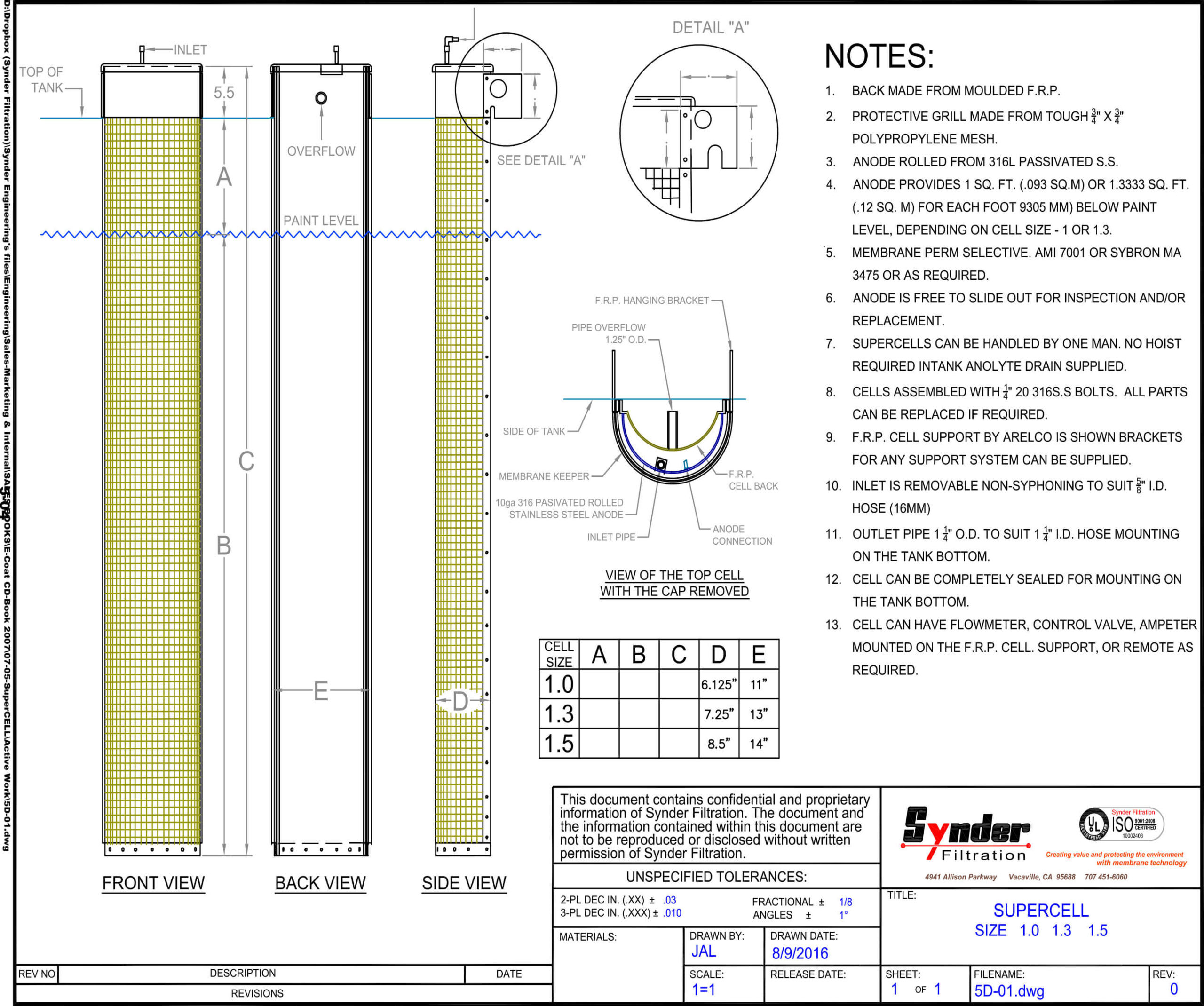
Daily Log Sheet